VOGONS


First post, by retardware

User metadata
Rank Oldbie
Rank
Oldbie

I learnt a lot in this forum.
So I got worried that the power supplies I am using are not damaging the hardware.

For this reason I built a makeshift power supply tester.
It is very simple.
There are two switches.
The first one turns the tester on.
This makes the PSU tester draw a "small load" of 2.45A on 5V (one 12V 50W bulb in series with 0.22ohms resistor), and 0.9A on 12V (relay, two fans and a 20ohms resistor).
The second switch adds some more bulbs, all in series with 0.22ohms resistor, increasing to "big load" of about 6.6A on 5V and 6.2A on 12V. (Slightly over spec for Molex connector, but okay for a few seconds)

DSCN8938.jpg

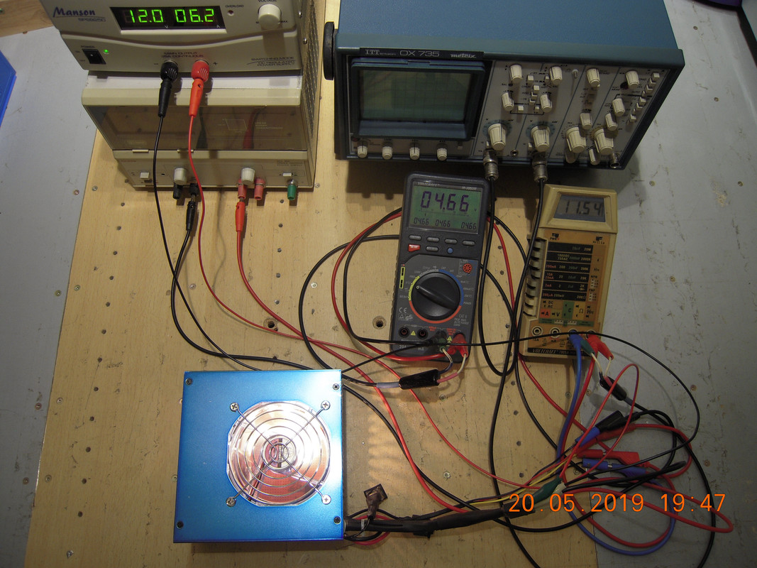
The tester is enclosed in a fancy blue PSU case with transparent fans. You see it running full load, connected to two variable PSUs via crocodile clamps at the Molex connector.

After I looked at my spare PSUs using the tester, I feel worried.

psutest-results-190520.png

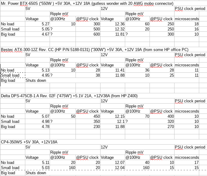
Only one of the four PSUs seems to be in-spec.

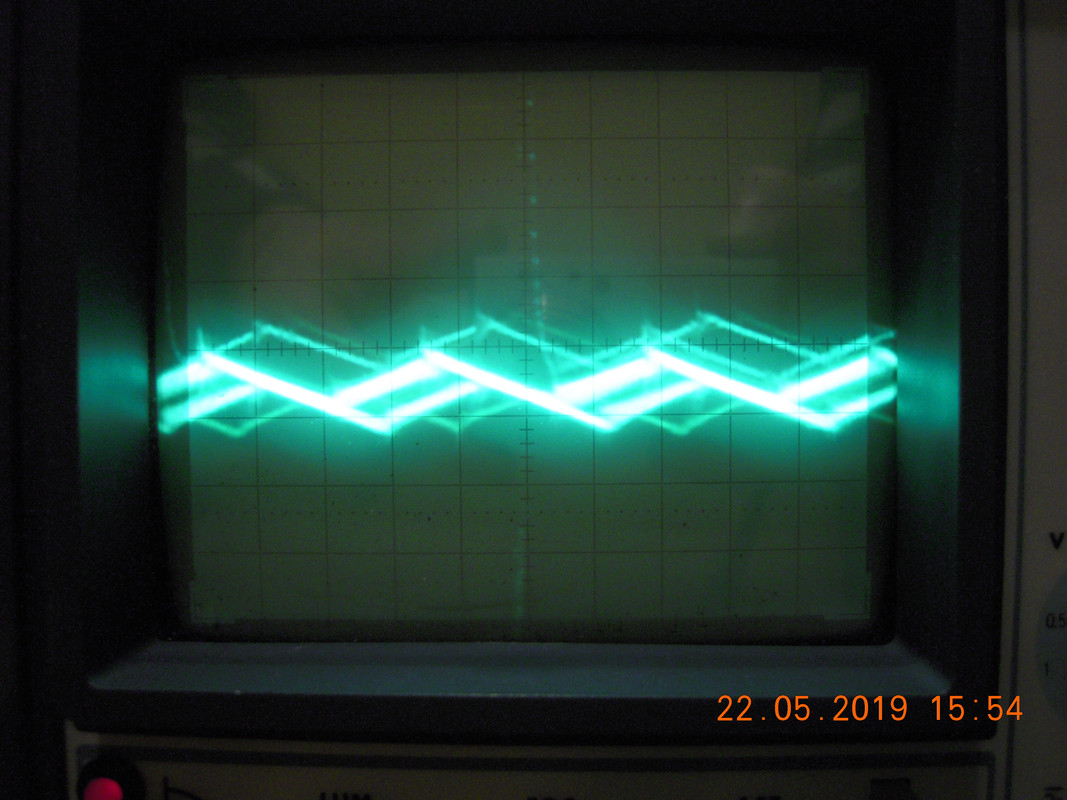
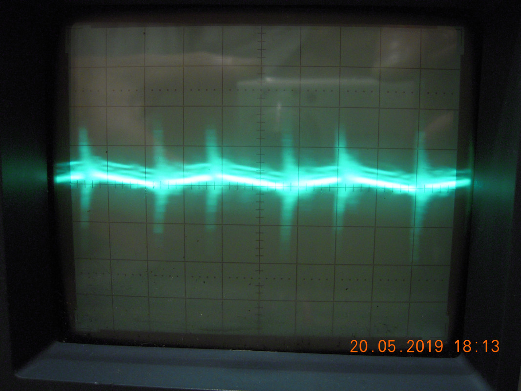
Mr. Power PSU at "small load" at 12V on the oscilloscope (50mV/cm, 5us/cm):

DSCN8927.jpg

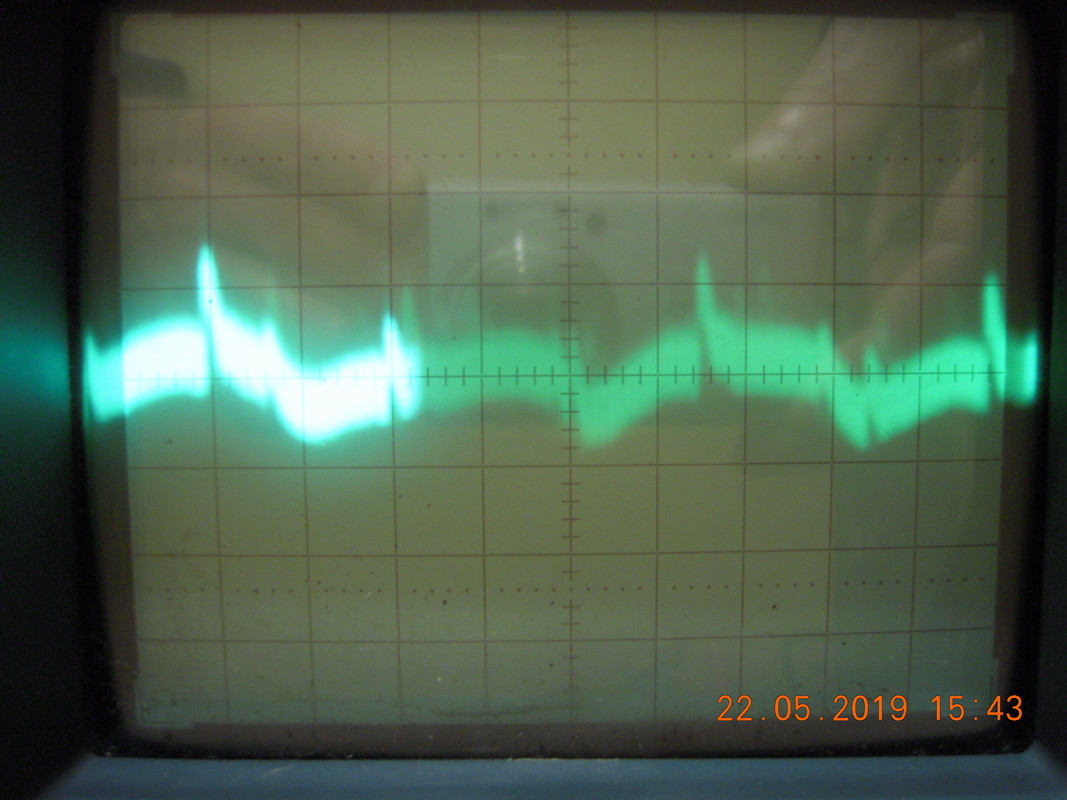
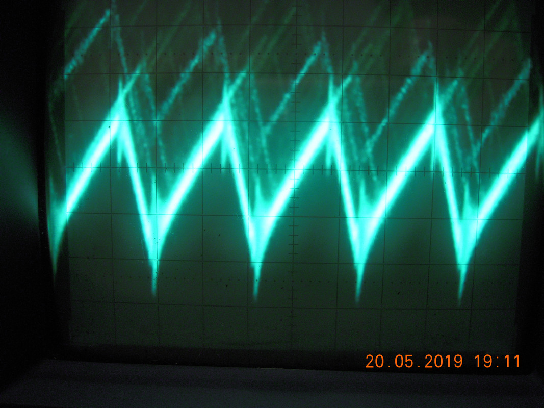
Bestec ATX-300-12Z at "small load" at 12V on the oscilloscope (5mV/cm, 5us/cm):

DSCN8931.jpg

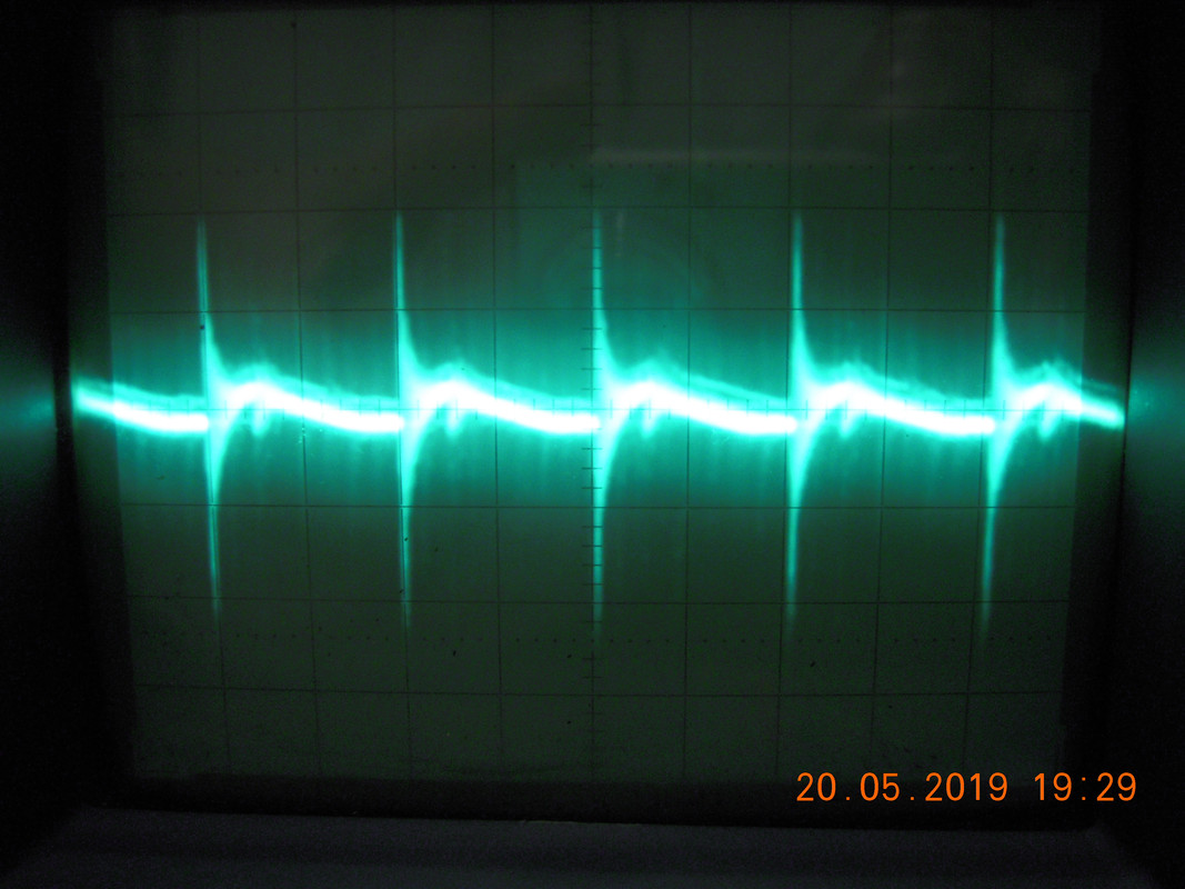
Delta DPS-475 at "small load" at 12V on the oscilloscope (50mV/cm, 5us/cm):

DSCN8933.jpg

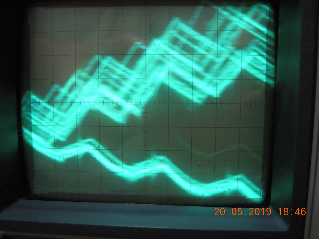
CP4-350WS at "small load" at 12V on the oscilloscope (10mV/cm, 5us/cm):

DSCN8929.jpg

Now my question, can I take the following conclusions?

Mr. Power: Caps on primary weak, dead on secondary?
Bestec: Still in spec?
Delta: Caps on primary weak, dead on secondary?
CP4: Caps on primary dead?

Reply 1 of 22, by Deunan

User metadata
Rank Oldbie
Rank
Oldbie

The caps could be weak, true, but some PSUs require all the output lines to be loaded. If the PSU has 3V3 output and you are not using it, but are trying to pull a lot of power from 5V/12V lines, chances are the 3V3 is going to creep up and trip over-voltage protection in the PSU. In general properly loading PC power supplies is not as easy as it might seem. Even if it works you might get weird issues like high ripple or spikes/ringing.

High-power PSUs are typically crap at very low loads as well, even modern digital 90%+ efficiency ones. In general if the load is below 10% of the rating, anything goes (well, as long as the voltages are still within +/- 10% tolerance). Same at loads close to max but here it's usually more ripple and voltage drops, in rather predictable fashion (scales with load).

Lastly, that setup of yours... Are those 30A wires? I use 36A and 15A depending on load and the 36A are high quality and very "soft" but thick and heavy. And even on those you can easily have measurable voltage drop after a meter or two. Pulling all that power from a single molex plug will get you 0.5V drop easily. If you have to do it this way, then pull power from one connector but measure voltages on another one - as in, different cable coming out of the PSU. Preferably do both, and you'll see the actual voltage on the PSU output and at the molex end so you'll know what the wires can take. AWG rating is one thing, but many of these wires came from China and copper is expensive..

Reply 2 of 22, by SirNickity

User metadata
Rank Oldbie
Rank
Oldbie

I'm not a super expert on SMPS diagnosis, but I do have some (enthusiast level) experience building DC-DC converters and linear PSUs. Assuming the design wasn't complete garbage to begin with, I would figure a ~400mV ripple to be a sign of bad output caps. Now it seems, for example on the Delta PSU, that's more peak-to-peak than RMS, and there are huge ringing spikes on the switching transitions. Seems to me like the filter caps are starting to increase in impedance and it's not damping those transients very well.

Definitely worth a better engineer's perspective, but OTOH, you really can't go wrong replacing old capacitors anyway.

Reply 3 of 22, by retardware

User metadata
Rank Oldbie
Rank
Oldbie
Deunan wrote:

The caps could be weak, true, but some PSUs require all the output lines to be loaded. If the PSU has 3V3 output and you are not using it, but are trying to pull a lot of power from 5V/12V lines, chances are the 3V3 is going to creep up and trip over-voltage protection in the PSU.

Oh, I didn't think of this at all! Maybe this was the reason for the PSUs to shut down...
Will add a multimeter to watch 3.3V, too.

Deunan wrote:

Lastly, that setup of yours... Are those 30A wires? I use 36A and 15A depending on load and the 36A are high quality and very "soft" but thick and heavy. And even on those you can easily have measurable voltage drop after a meter or two.

These are thin wires. 0.75mm2. 1m already made ~0.4V drop.
Will need to get thicker ones like you describe 😀
Inside the "psu tester", I used thicker but less flexible wires to reduce drop.

Deunan wrote:

Pulling all that power from a single molex plug will get you 0.5V drop easily. If you have to do it this way, then pull power from one connector but measure voltages on another one - as in, different cable coming out of the PSU. Preferably do both, and you'll see the actual voltage on the PSU output and at the molex end so you'll know what the wires can take. AWG rating is one thing, but many of these wires came from China and copper is expensive..

Wow, great idea!
So one easily can find out the true wire rating... thats very useful, too! Thank you very much!

Reply 4 of 22, by gdjacobs

User metadata
Rank l33t++
Rank
l33t++

Generally it's recommended to load each rail with the same proportion of maximum from the load table.

All hail the Great Capacitor Brand Finder

Reply 5 of 22, by retardware

User metadata
Rank Oldbie
Rank
Oldbie
SirNickity wrote:

Now it seems, for example on the Delta PSU, that's more peak-to-peak than RMS, and there are huge ringing spikes on the switching transitions. Seems to me like the filter caps are starting to increase in impedance and it's not damping those transients very well.

Definitely worth a better engineer's perspective, but OTOH, you really can't go wrong replacing old capacitors anyway.

Thank you, this is what I thought (from my SMPS n00b perspective).
So I will replace the caps, if only to see what the difference (if any) will be.

gdjacobs wrote:

Generally it's recommended to load each rail with the same proportion of maximum from the load table.

This would be optimal.
I really need to get an ATX power connector from a dead ATX mobo, to include 3.3V test.

But as at least the CP4-350WS is being intended to work as a test bench PSU for AT class computers, I don't know what to do with 3.3V there.
With the common ATX-P8P9 adapters 3.3V also does not get any load, so I think I need to know how the PSU behave in that case, too.

Actually that one PSU was in use of my main computer when it was new, and later swapped for a Seasonic one. When I recently opened the PSUs to judge their guts, I found all secondary side electrolytics bloated, some even burst open.
I replaced them with some random used but good-looking low esr electrolytics I found lying around. (Well, not that random, just slightly higher values of these which I had no exact replacements for).
Maybe this explains why the extreme 100Hz ripple while looking okay on the switching frequency?

Reply 6 of 22, by Deunan

User metadata
Rank Oldbie
Rank
Oldbie
retardware wrote:

I found all secondary side electrolytics bloated, some even burst open.
I replaced them with some random used but good-looking low esr electrolytics I found lying around.

You need to use low-ESR caps on outputs out of switching PSUs. The lower ESR, the less ripple there will be. You can also try one notch higher capacity values but don't over do it. It's not safe for the diodes and also the energy in high-power PSU is stored in the output inductors, not the caps. So if the manufacturer cheaped out on inductors you can't really do much with the capacitors alone.

If you don't have a low-ESR cap for replacement but suspect that the original has degraded and you want to test it, there is a temporary workaround. Solder a ceramic disc capacitor of at least 100nF directly to the leads of the suspected cap on the bottom side of the mobo. Then investigate the ripple again with the scope. If it got visibly better that cap needs to go.
Values of 220 or 470nF are even better but it has to be a non-inductive capacitor (like ceramic disc are). This temporary fix can be a permanent one if the new "bypass" cap can be safely mounted (on either side of the PCB) without the risk of shorting something. But you can't use wires, the leads have to be very short or else there is no point in doing this.

Reply 7 of 22, by luckybob

User metadata
Rank l33t
Rank
l33t

I think you should read through this: http://www.jonnyguru.com/testing-methodology/

That person has been reviewing powersuppies for like 15 years now. Nobody I know of has even come close to testing as well as he has.

It is a mistake to think you can solve any major problems just with potatoes.

Reply 8 of 22, by gdjacobs

User metadata
Rank l33t++
Rank
l33t++
Deunan wrote:
You need to use low-ESR caps on outputs out of switching PSUs. The lower ESR, the less ripple there will be. You can also try on […]
Show full quote
retardware wrote:

I found all secondary side electrolytics bloated, some even burst open.
I replaced them with some random used but good-looking low esr electrolytics I found lying around.

You need to use low-ESR caps on outputs out of switching PSUs. The lower ESR, the less ripple there will be. You can also try one notch higher capacity values but don't over do it. It's not safe for the diodes and also the energy in high-power PSU is stored in the output inductors, not the caps. So if the manufacturer cheaped out on inductors you can't really do much with the capacitors alone.

If you don't have a low-ESR cap for replacement but suspect that the original has degraded and you want to test it, there is a temporary workaround. Solder a ceramic disc capacitor of at least 100nF directly to the leads of the suspected cap on the bottom side of the mobo. Then investigate the ripple again with the scope. If it got visibly better that cap needs to go.
Values of 220 or 470nF are even better but it has to be a non-inductive capacitor (like ceramic disc are). This temporary fix can be a permanent one if the new "bypass" cap can be safely mounted (on either side of the PCB) without the risk of shorting something. But you can't use wires, the leads have to be very short or else there is no point in doing this.

Substituting caps with too low an ESR can lead to instability for certain circuits controlled by feedback. Try to use filter caps with a similar ESR to what they're replacing. Not exact, but in the ballpark should be fine.

All hail the Great Capacitor Brand Finder

Reply 9 of 22, by retardware

User metadata
Rank Oldbie
Rank
Oldbie

@Deunan

Great trick, this "bypass" testing! I guess this can come very handy.

@luckybob

Good suggestions in the article.
Maybe I should get some dummy loads like a 5.25 FH HDD just to see the effect of a big motor.

But my main intention building this tester contraption is to make sure that my PSUs are actually safe for the electronics.
Considering what big ripple can do to HDDs and boards, I did not feel well anymore using "working" but actually untested PSU. I want to be sure my rare stuff doesn't get damaged by something invisible like radiation.

gdjacobs wrote:

Substituting caps with too low an ESR can lead to instability for certain circuits controlled by feedback. Try to use filter caps with a similar ESR to what they're replacing. Not exact, but in the ballpark should be fine.

Ouch! Good to know!
The bad thing is I am not skilled enough to find out which kind of cap it is.
When I find it near the pi coil, I think its safe to assume its low esr.

But as I am now going to replace the other caps in the CPS350, 10uF 50V and 100uF 50V on the secondary side, and 2x 470uF 200V on the primary, I now wonder whether I should get "normal" ones instead of low ESR...

Reply 10 of 22, by SirNickity

User metadata
Rank Oldbie
Rank
Oldbie

Don't overthink it. Honestly, the only way to do it "right" is to know the exact requirements of the switching circuit, and the properties of all the related components, and engineer the solution. Unless you're designing a new PSU though, there's just no return on that investment of time and effort. So make some assumptions. Yes, if you fall outside the safety bounds of the switching feedback loop, it'll become unstable. That's always a risk. But probably not super likely, so just pick a good brand (I use Nichicon, but any reputable maker will do), find the ones with the highest ripple current rating and lowest ESR that have similar capacity ratings and at least as high voltage rating for that package size, and go with that.

I've refurbished about a dozen AT and old ATX supplies now using this method, and I have exactly one that seems unhappy with me. It's from one of those small form factor Unisys terminals (a Pentium 133 in this case), which has a tiny tiny integrated AC-to-DC PSU with barely enough grunt to run the system, so it's possible I'm just overloading the +5V rail. Something is whining (either the input choke or the transformer, hard to tell) and there's a lot of carrier-frequency ripple on the output. I've yet to troubleshoot further. It may be a loop stability thing, but it's hard to test it out-of-system due to the proprietary motherboard connector.

Reply 11 of 22, by retardware

User metadata
Rank Oldbie
Rank
Oldbie

Yes the question of introducing instabilities...

I now have replaced all the other caps with some new standard caps (no specially low esr).
As the local dealer had no matching 470uf mains caps there, I just took two Nippon Chemicon 270uf 450V (I think this will be sufficient for the probably not more than 60, 70W I need from the PSU).
The 100Hz ripple got much better. But...

...what worries me now is what I see in the scope screen.
(I am not sure whether I just overlooked it before I replaced the caps or it is new)

There are BIG spikes.
Following is with 5us/cm and 10mV/cm. The output ripple would be fine if it were not for these spikes.
(See in middle and left boundary of screen)

DSCN8948.jpg

With 50ms/cm and 20mV/cm it looks like this:
(Notice the very short-term high overshooting, hard to see in the photo)

DSCN8942.jpg

Now I am thinking about taking a separate power supply for the relais and the fans of that PSU tester.
I also have not yet made another measurement adapter to measure from another Molex cable, as Deunan suggested (still need to get more banana plugs).

Maybe these spikes are just the effects from the fans?
Or are such things just that what you meant with "instabilities"?

Reply 12 of 22, by luckybob

User metadata
Rank l33t
Rank
l33t

Dude, you are making mountains out of molehills.

10mv p2p? What is the target voltage? Anything less than 5% isn't worth the effort, and once you get below 2% the margin of error is what you are reading at that point with that hardware. Local regulation and decoupling will sort everything out.

look at these power supplies: http://www.chromaate.com/product/dc_power_sup … y_62075h30n.htm

The are assembled by grey-bearded, nude virgins during the light of a new moon on Tuesdays. Those are $100,000+ supplies and even their datasheets claim +/- 20mV.

My general rule of thumb is to keep ripple under 5% and never use more than 2/3 of the rated capacity of any power supply. Everything else is just a waste of time unless you are in a lab.

It is a mistake to think you can solve any major problems just with potatoes.

Reply 13 of 22, by retardware

User metadata
Rank Oldbie
Rank
Oldbie

The pics show the 12V line, and the second photo does not show that the overshooting covers the whole screen.
That's at least 160mV... the ATX specification allows 120 only.
But on the other hand, if one 5% (600mV) overshoot one microsecond maybe every 5-10 milliseconds doesn't do much damage or instability, then this PSU might be acceptable as it is now?

Reply 14 of 22, by SirNickity

User metadata
Rank Oldbie
Rank
Oldbie

What you're seeing is probably from the inductor flyback. These should be clamped, worse-case, to a diode drop by the freewheeling diodes. Did you try the ceramic bypass cap across the pins of the bulk cap? That's exactly the kind of stuff it would filter out. Particularly important if your bulk caps are not low-ESR.

Reply 15 of 22, by retardware

User metadata
Rank Oldbie
Rank
Oldbie

Thanks @SirNickity, this sounds very plausible!

Will have to get some ceramics tomorrow and add them.
I'll also check the freewheeling diodes whether they are still good.

Reply 16 of 22, by Deunan

User metadata
Rank Oldbie
Rank
Oldbie

Was this tested with at least 10% load? Without load noise in the output is usually higher for switching-mode PSUs - and that's normal.
However if you get spikes like these with pure resistive load (like the 12V bulbs you have) then either something is broken, or the PSU was crap to begin with (poor design). It's best to measure that near the load as that is where you want clean power. Sometimes even the cable from the PSU to the load is inductive enough to clean up some HF noise.

Trust me, even 50mV ripple at the load on 5V line is not an issue for logic chips. The ripple the chips themselves generate is sometimes worse, and that's exactly why TTL has such huge safety margins between 0 and 1, and why 1 starts as low as 2.4V. NMOS chips usually can't even output anything above 4V at single MHz transitions and it all still works.

To sum it up: Without load all you care is the voltages don't go beyond +/- 10%. Ripple is irrelevant unless added to the mean voltage causes it to go beyond the 10%. Spikes and ringing - same thing. Even very high spikes but short in duration carry almost no energy.
With at least 10% load the ripple should be reasonable (though that depends on the quality of the PSU) and spikes should be all but gone. 10-20mV ringing could be crappy PSU, too long cables, or just a measurement error (scope probes not 10:1, too long or badly grounded).

Oh and this is always valid: Never stick your scope probes into the primary side of a mains-powered switching-mode PSU. Unless you know very well what you are doing and why. Even then, think twice. I know this rule, I was taught this rule, I obey this rule, and yet I still made a mistake once.

Reply 17 of 22, by retardware

User metadata
Rank Oldbie
Rank
Oldbie
Deunan wrote:

Was this tested with at least 10% load? Without load noise in the output is usually higher for switching-mode PSUs - and that's normal.

All the scope pictures are with 2.7A on 5V and 0.9A on 12V.

Deunan wrote:

However if you get spikes like these with pure resistive load (like the 12V bulbs you have) then either something is broken, or the PSU was crap to begin with (poor design). It's best to measure that near the load as that is where you want clean power. Sometimes even the cable from the PSU to the load is inductive enough to clean up some HF noise.

Measurements were taken directly at load point (where the resistor/bulbs connection junction from).
To make sure the fans do not factor in, I'll modify the PSU tester so that it takes the fan supply from an external PSU.
If the spikes then still are there, they must come from the PSU I am trying to fix.

Deunan wrote:

To sum it up: Without load all you care is the voltages don't go beyond +/- 10%. Ripple is irrelevant unless added to the mean voltage causes it to go beyond the 10%. Spikes and ringing - same thing. Even very high spikes but short in duration carry almost no energy.
With at least 10% load the ripple should be reasonable (though that depends on the quality of the PSU) and spikes should be all but gone. 10-20mV ringing could be crappy PSU, too long cables, or just a measurement error (scope probes not 10:1, too long or badly grounded).

Except for these big spikes the PSU seems good.
Does ringing count as "ripple" in the ATX spec? Or are there different limits for that?

Deunan wrote:

Oh and this is always valid: Never stick your scope probes into the primary side of a mains-powered switching-mode PSU. Unless you know very well what you are doing and why. Even then, think twice. I know this rule, I was taught this rule, I obey this rule, and yet I still made a mistake once.

When I was at school, I made a lot of money by picking up abandoned color TVs from the street, fixing and selling them.
These normally had no mains-separated power supply. Usually one pin of the cord was chassis ground, then it was easy, just make sure it is plugged the way around that chassis is not live. I hated those that used a 4-diode rectifier, as their chassis was at the DC ground. These I treated extremely respectfully, usually not measuring when plugged in.

And even with these with 1-diode-rectifier I always felt uncomfortable when the oscilloscope probe sparked when I checked what was going on at the HOT, usually something around 600-900V. I hate that high voltage stuff. 😵

And even though I always kept one hand in the trousers, I made some mistakes. I still remember accidentally touching a spot in the convergence circuitry (some 820V). That was a good zap...

(Just curious, what was the mistake you once made?)

So don't worry, I am not going to do live PSU testing, at least not without an insulation transformer. 😀
They aren't built for convenient testing while open, like good TV sets were.
One would at least need some board holder, like the QC departments in the factories have.

Reply 19 of 22, by gdjacobs

User metadata
Rank l33t++
Rank
l33t++
retardware wrote:

Ouch! Good to know!
The bad thing is I am not skilled enough to find out which kind of cap it is.
When I find it near the pi coil, I think its safe to assume its low esr.

Yes, generally. Lower ESR on the Pi filter will reduce the output ripple.

To be safe, find the MFR -- use the link in my signature for the weird ones, they've got pictures of pretty much everyone's logo, vent style, and colour scheme. Combined with the data written on the cap (series code, voltage, capacitance) and case size, you can get the spec ESR from the MFRs datasheet. I have a fairly good, commonly used library of datasheets linked below.
http://www.paullinebarger.net/DS/

For polymodding, use capacitors with similar ESR and sufficient voltage withstand. Nominal capacitance is the least important parameter for typical low ESR elcap applications.

All hail the Great Capacitor Brand Finder