VOGONS


First post, by DAVE86

User metadata
Rank Newbie
Rank
Newbie

Hello

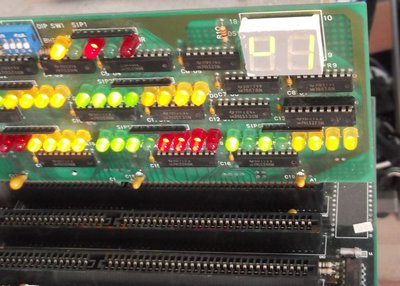
I found this old post card on the flea market. Made in 1993, standard ISA 16 bit bus. It has a pair of seven segment display, lots of leds, some dip switches and one tactile switch. I could find any info about it. Has a lot of 74 series logic and some bcd to hex converter ICs.
It was a bit damaged when I got it. C17 cap was cracked or exploded and SW1 switch was missing. I fixed it up and tested in in a 486 mobo. It seems to work ok but it isn't exactly showing HEX numbers. I tested all the segments seperately and they ligth up ok.
It seems to display symbols (maybe). See first pic. The symbols aren't corresponding to award or ami post codes. I'm not familiar with the function of the leds either...
Has anyone seen this type of diagnostic card before?

Attachments

  • DSCF6740.jpg
    Filename
    DSCF6740.jpg
    File size
    284.29 KiB
    Views
    413 views
    File license
    Fair use/fair dealing exception
  • DSCF6737.jpg
    Filename
    DSCF6737.jpg
    File size
    442.59 KiB
    Views
    413 views
    File license
    Fair use/fair dealing exception
  • DSCF6736.jpg
    Filename
    DSCF6736.jpg
    File size
    502.69 KiB
    Views
    413 views
    File license
    Fair use/fair dealing exception

Reply 2 of 5, by Tronix

User metadata
Rank Member
Rank
Member

You can simply test your card with help DEBUG.EXE. Run debug.exe from MS-DOS or Windows 9x command line, then use "o(output)" command for output byte to port. Usually post-card used 80 hex I/O port, but some strange system uses 81h or 84h I/O ports. Maybe you can select port with SW1 dip-switches. on post-card. Then type -o80 AA and press Enter. You must see "AA" at led display. So, you can experiment with -o81 AA, -o84 AA, etc. Then try change numbers to display, ex: -o80 00, -o80 01, -o80 02, etc.

Leds are indicated data and address bits on ISA bus, D0..D15 (16 bit data), A0..A23 (24 bit address). LEDS on top indicated special control ISA signals like BHE, RESET and other (i can't recognize from picture).

https://github.com/Tronix286/

Reply 3 of 5, by mdog69

User metadata
Rank Newbie
Rank
Newbie

The 7 seg displays are driven by a pair of 7447 BCD to 7 segment decoders. Values between 0 and 9 will display correctly. Values between A and F will display "hieroglyphics" not hex digits. (The 7447 dataset will allow you to decode these into "proper" hex.)

Last edited by mdog69 on 2019-08-01, 23:25. Edited 1 time in total.

Reply 4 of 5, by Tronix

User metadata
Rank Member
Rank
Member
mdog69 wrote:

Values between A and F will display "hieroglyphics" not hex digits. (The 7447 dataset will allow you to decode these into "proper" hex.

Ooops, yes, i fogot about it. See http://i.imgur.com/tT11p6B.png table to decode "hieroglyphics" to HEX-digits. At first picture we see C1 post-code.

https://github.com/Tronix286/

Reply 5 of 5, by DAVE86

User metadata
Rank Newbie
Rank
Newbie
mdog69 wrote:

The 7 seg displays are driven by a pair of 7447 BCD to 7 segment decoders. Values between 0 and 9 will display correctly. Values between A and F will display "hieroglyphics" not hex digits. (The 7447 dataset will allow you to decode these into "proper" hex.)

Thanks! Almost started swapping out chips at random. I should have consulted the datasheets 😊