VOGONS


First post, by McBierle

User metadata
Rank Member
Rank
Member

Hi, i have a problem with this i/o card i don't understand.

IMG_20200218_194954.jpg
Filename
IMG_20200218_194954.jpg
File size
57.4 KiB
Views
550 views
File license
Public domain
IMG_20200218_195000.jpg
Filename
IMG_20200218_195000.jpg
File size
117.92 KiB
Views
550 views
File license
Public domain

No matter what jumper settings i choose everything seems to be as if i jumpered 1-2.
I tested a bit around and i will take jumper 4 (LPT enable/disable) as an example:
1-2 is enable, and even when jumpered to 2-3 it is still on. Pin 2 is connected to the chip and pin 3 connects to ground via that 10k resistor.
When using a direct connection to ground (jumper cable) without a resistor the lpt turns off.

Am i missing something? Why it is notr working as intended?

Greetings!

Reply 1 of 6, by SirNickity

User metadata
Rank Oldbie
Rank
Oldbie

Are you sure? That's not generally how it works. E.g., the chip's pin (2) will usually be pulled up to +5V or down to Gnd to provide a default state just in case the jumper is missing or ineffective, and then Pin 1 will be +5 and Pin 3 will be Gnd (for example). If you set the state of pin 2 THROUGH a resistor to Gnd, then either pin 2 has to have a very weak pullup to +5v (100K? 500K?) or it's floating -- which is just bad design.

It's also possible that, for example, pin 1 is the chip's IO pin, pin 2 is tied to ground via resistor, pin 1 and 2 are connected, and pin 3 is tied to +5V. That way, if the jumper is in 1-2 position, it's not really doing anything -- just shorting the link that already exists on the PCB anyway. But, if you move the jumper to 2-3, you're over-riding the R to Gnd with +5V, and since 1-2 are connected, that sets the voltage on Pin 1 as well.

Reply 2 of 6, by McBierle

User metadata
Rank Member
Rank
Member

Ok i had time to poke around.

1.
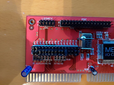
JP1-6 and 8-11 have no connection on pin 1; and are connected to gnd via 10k resistors.
They only have an effect when i put them directly to gnd (1k also works).

2.
JP7 and 12-15 are IRQ jumpers (LPT/COM) and go to the chip and irq-buslanes, without resistors.

3.
Jumpers for:
- COM A/B enable/disable
- COM adress
- LPT enable/disbale
- LPT Bidirectional/Output
are going to the controller chip and further to this "HM8388P" dip20.

4. Jumper 6 "LPT Port"
pin 1 : not connected
pin3 : resistor -> gnd
pin2: controller chip -> cap (c4) -> gameport -> gnd

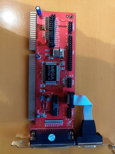
5. Strange gameport, what are 10pin gameports doing on PCs.

6. HMC HM8388P
I couldn't find a datasheet.
Pins:
1 : 12v
2-7: COM/LPT as descibed in 3.
8-9: NC
10: gnd

11-13: NC
14-19: COM-Ports
20: -12V

Measurements:
2-7: 5V... or when i pull them directly to ground (not going through the 10k resistors) change to 0V.
14-19: changing between -12/+12V depending on enabled/disabled COM-ports.

Some more things:
I got curious and pulled out the diodes through which the +-12V are going.
- The -12V side goes dark
- The +12V side gets from pin 2-7 5V.

So it seems the 5V for the defined state is originating at the controller chip.

Anyways what could be defective so that the jumpers have no effect. I mean it can't be a design mistake, or could it be that the wanted to put in 1k resistor and mistakenly got 10k ones?

Greetings and good night!

Reply 3 of 6, by McBierle

User metadata
Rank Member
Rank
Member

Come on, i'm in the magical Halls of Wisdom and no one has an idea?

Well i found some 1k smd resistors on a dead board and successfully relocated one to the controller...

Greetings!

but whyyyyyyyyy??????

Reply 4 of 6, by SirNickity

User metadata
Rank Oldbie
Rank
Oldbie

Tough to say. Is pin 1 actually n/c, or is there a burnt/broken/corroded trace somewhere? What's the controller chip? (You say it's in parallel with the HM chip on that block of jumpers.) Is there maybe a problem with the on-chip pull-up, where it's providing a stronger pull-up than it's supposed to? Maybe the 10K Rs were replaced by somebody? Maybe it's just a piece of junk card. 😉

Reply 5 of 6, by Horun

User metadata
Rank l33t++
Rank
l33t++
SirNickity wrote on 2020-02-21, 22:03:

Maybe it's just a piece of junk card. 😉

🤣 To be honest never saw a full red colored ISA HD card until now. I see lots of other ISA hd cards for sale for $10-20 on ebay and other sites but never a red one. Maybe that is an omen (I tag bad parts with a red sticker).

Hate posting a reply and then have to edit it because it made no sense 😁 First computer was an IBM 3270 workstation with CGA monitor. Stuff: https://archive.org/details/@horun