CoffeeOne wrote on 2020-05-01, 11:40:OK, that's interesting.
So the board is not completely dead at least (?)
Are all 4 cpus intel?
That means at external 25MHz the […]
Show full quote
Parni wrote on 2020-05-01, 11:11:
OK, I explored further, DX 33MHz doest heat up at all, DX2 66MHz (both WB and without) a bit and 50Mhz DX2 heated up quite nicely. However no POST 😒
Could it just be the BIOS that is defected?
OK, that's interesting.
So the board is not completely dead at least (?)
Are all 4 cpus intel?
That means at external 25MHz the cpus get warm? Did you check also the DX33 and the DX2-66 with external 25MHz? Or is one of the cpus a cyrix?
Time to double check the jumpers for cpu-type setting!
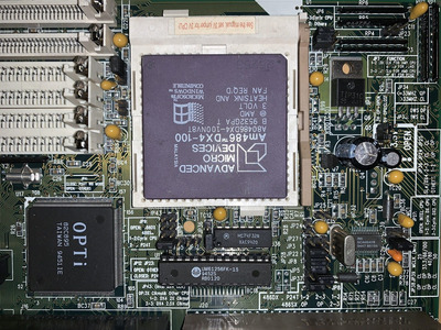
Yes, all the CPU's are Intel, also tried with AMD 100Mhz. I didn't try with 25Mhz External, the CPU frequency selections variate a bit depending which manual look.
Manual 1 (From Total Hardware 1999 index)
Speed JP38 JP39
25MHz Open Closed
33MHz Closed Open
40MHz Open Open
50iMHz Open Closed
50MHz Closed Closed
66iMHz Closed Open
75iMHz Open Closed
80iMHz Open Open
100iMHz Closed Open
Manual 2 (scanned- assumably the original one?)
Speed JP38 JP39
25MHz Open Closed
33/66/100MHz Closed Open
50MHz Open Open
50MHz Closed Closed
When I got the DX2 50Mhz warmed up is had the JP38 and 39 closed, wonder what is the i50Mhz, does "i" stand for Intel?
With the other jumpers I have been very carefully, verified many times.
There is no multiplier jumper in this board.