VOGONS


Problems with QDI v4p895p3/smt V5.0

Topic actions

Reply 40 of 99, by CoffeeOne

User metadata
Rank Oldbie
Rank
Oldbie
Parni wrote on 2020-05-01, 10:09:

Im wondering one thing about the manual, it's quite specific of the memory configuration regarding "Single bank" and "Dual-bank" memorys, how do I tell which one my memorys are?
The manual can be found from here: http://www.elhvb.com/mboards/qdi/895p3s5.pdf

yes, that's really strange:
You are talking of JP42, right? How did you set it (I guess 1-2)?

Reply 41 of 99, by computerguy08

User metadata
Rank Member
Rank
Member
CoffeeOne wrote on 2020-05-02, 12:11:
Parni wrote on 2020-05-01, 10:09:

Im wondering one thing about the manual, it's quite specific of the memory configuration regarding "Single bank" and "Dual-bank" memorys, how do I tell which one my memorys are?
The manual can be found from here: http://www.elhvb.com/mboards/qdi/895p3s5.pdf

yes, that's really strange:
You are talking of JP42, right? How did you set it (I guess 1-2)?

To start with, JP42 controls whether Bank 0 is enabled or not (basically it controls whether you can use 30pin and 72pin SIMMs simultaneously or not).

CoffeeOne wrote on 2020-05-02, 11:49:
True, it's really confusing: On the board and in the second manual, there is the block (from up to down): JP27 JP3 JP22 JP8 JP5 […]
Show full quote

True, it's really confusing:
On the board and in the second manual, there is the block (from up to down):
JP27
JP3
JP22
JP8
JP5

But in the figure of the first manual:
it is
JP27
JP3
JP22
JP5
JP8

so the 2nd manual seems to be good, you are right.

AND there is a table on the board with the settings for
JP3, JP5, JP8

so not in the order as the jumpers are on the board, moreover JP22 is in between. Oh my god.
That does not make it more easy.

About JP1, that's the maybe most important one.
It should be either closed or open.

But there seems another empy pin beside it. ???? What it is?

A bit of expanation. JP22 isn't mentioned on the silkscreen (even though it is between other CPU jumper settings), because it is permanently set in the 1 & 2 position, you wouldn't change it anyway.
I imagine the manufacturer used that jumper for something else in other board revisions, they didn't bother to remove it in this one for some reason. You can check the manual.

Their order doesn't matter in practice, they all control the CPU type.

For JP1 it's the same story, they had a different voltage reg in other board revisions and had to use 3 pins instead of 2.

I know, jumper settings on cheap/unbranded 486 boards is one of the worst PC designs, but it isn't rocket science. You just need some patience.

Reply 42 of 99, by Parni

User metadata
Rank Member
Rank
Member
computerguy08 wrote on 2020-05-02, 07:15:
Parni wrote on 2020-05-01, 16:39:

About the voltage regulator, should't i get out something with DX processor (5V) jumper selection?

The voltage regulator will get bypassed in 5V mode (in this case the CPU is fed power directrly from the PSU).

It would be a good idea to probe the voltage from the CPU socket directly (when there is no CPU installed), using a solid copper wire or a needle to poke inside the socket.

OK, I made the measurements! 😀
With 3V jumper setting (JP1 open) I get 3.469V from VCC legs and with 5V jumper setting (JP1 closed) I get 5.094V-5.115V from the VCC legs.

Reply 43 of 99, by Parni

User metadata
Rank Member
Rank
Member
CoffeeOne wrote on 2020-05-02, 11:49:
True, it's really confusing: On the board and in the second manual, there is the block (from up to down): JP27 JP3 JP22 JP8 JP5 […]
Show full quote
computerguy08 wrote on 2020-05-02, 11:31:
CoffeeOne wrote on 2020-05-02, 11:07:

I am quite sure, that both manuals that you attached, do not match 100%.
So ignore it, and use as only reference the writings on the board.

The second manual seems to match his board, what makes you think it doesn't?

All jumpers seem to be in the same position and markings as in the manual.

True, it's really confusing:
On the board and in the second manual, there is the block (from up to down):
JP27
JP3
JP22
JP8
JP5

But in the figure of the first manual:
it is
JP27
JP3
JP22
JP5
JP8

so the 2nd manual seems to be good, you are right.

AND there is a table on the board with the settings for
JP3, JP5, JP8

so not in the order as the jumpers are on the board, moreover JP22 is in between. Oh my god.
That does not make it more easy.

About JP1, that's the maybe most important one.
It should be either closed or open.

But there seems another empy pin beside it. ???? What it is?

JP1 has just 2 pins, I rest my jumper on the other pin 😀 the picture bluffs, there are not 3pins..

Reply 44 of 99, by computerguy08

User metadata
Rank Member
Rank
Member
Parni wrote on 2020-05-02, 18:42:

OK, I made the measurements! 😀
With 3V jumper setting (JP1 open) I get 3.469V from VCC legs and with 5V jumper setting (JP1 closed) I get 5.094V-5.115V from the VCC legs.

Great! It means that the voltage regulation is working.

I would suggest you to configure the motherboard using the second manual and a 486DX or 486SX (at least for now). No DX2 or DX4 stuff, just 486, 5V.

Reply 45 of 99, by Parni

User metadata
Rank Member
Rank
Member
computerguy08 wrote on 2020-05-02, 18:47:
Parni wrote on 2020-05-02, 18:42:

OK, I made the measurements! 😀
With 3V jumper setting (JP1 open) I get 3.469V from VCC legs and with 5V jumper setting (JP1 closed) I get 5.094V-5.115V from the VCC legs.

Great! It means that the voltage regulation is working.

I would suggest you to configure the motherboard using the second manual and a 486DX or 486SX (at least for now). No DX2 or DX4 stuff, just 486, 5V.

Tried with SL - DX486 jumper settings, doesn't post 😒
Turbo switch on/off doesn't help either.

v4p895p3-3-DX.jpg
Filename
v4p895p3-3-DX.jpg
File size
546.95 KiB
Views
1251 views
File license
CC-BY-4.0

Reply 46 of 99, by CoffeeOne

User metadata
Rank Oldbie
Rank
Oldbie
Parni wrote on 2020-05-02, 19:03:
computerguy08 wrote on 2020-05-02, 18:47:
Parni wrote on 2020-05-02, 18:42:

OK, I made the measurements! 😀
With 3V jumper setting (JP1 open) I get 3.469V from VCC legs and with 5V jumper setting (JP1 closed) I get 5.094V-5.115V from the VCC legs.

Great! It means that the voltage regulation is working.

I would suggest you to configure the motherboard using the second manual and a 486DX or 486SX (at least for now). No DX2 or DX4 stuff, just 486, 5V.

Tried with SL - DX486 jumper settings, doesn't post 😒

v4p895p3-3-DX.jpg

OK, so no progress unfortunately.
When you turn it on and wait 5 minutes. How warm is the cpu then?

Reply 47 of 99, by Parni

User metadata
Rank Member
Rank
Member
CoffeeOne wrote on 2020-05-02, 19:09:
Parni wrote on 2020-05-02, 19:03:
computerguy08 wrote on 2020-05-02, 18:47:

Great! It means that the voltage regulation is working.

I would suggest you to configure the motherboard using the second manual and a 486DX or 486SX (at least for now). No DX2 or DX4 stuff, just 486, 5V.

Tried with SL - DX486 jumper settings, doesn't post 😒

v4p895p3-3-DX.jpg

OK, so no progress unfortunately.
When you turn it on and wait 5 minutes. How warm is the cpu then?

Doesn't heat at all

Reply 48 of 99, by computerguy08

User metadata
Rank Member
Rank
Member

You should set JP36 to 1&2, JP24 and JP25 to open. Not guaranteed to fix the problem, but worth a try.

Make sure JP26 isn't set in clear CMOS mode.

A POST card would be helpful in these kind of situations.

Reply 49 of 99, by Parni

User metadata
Rank Member
Rank
Member
computerguy08 wrote on 2020-05-02, 20:07:

You should set JP36 to 1&2, JP24 and JP25 to open. Not guaranteed to fix the problem, but worth a try.

Make sure JP26 isn't set in clear CMOS mode.

A POST card would be helpful in these kind of situations.

Hi, I tried this. Doesn't work 😒

Reply 50 of 99, by Parni

User metadata
Rank Member
Rank
Member

I found this thread: https://www.experts-exchange.com/questions/10 … rd-problem.html

It reads: "I can't find the manual, but I know that there is only a few certain memory configurations the motherboard can take."

Again I'm starting to wonder could this be just a memory configuration issue, could someone explain what are the "single" and "double" bank memory mentioned in this manual: http://www.elhvb.com/mboards/qdi/895p3s5.pdf

Reply 51 of 99, by computerguy08

User metadata
Rank Member
Rank
Member
Parni wrote on 2020-05-02, 20:17:

I found this thread: https://www.experts-exchange.com/questions/10 … rd-problem.html

It reads: "I can't find the manual, but I know that there is only a few certain memory configurations the motherboard can take."

Again I'm starting to wonder could this be just a memory configuration issue, could someone explain what are the "single" and "double" bank memory mentioned in this manual: http://www.elhvb.com/mboards/qdi/895p3s5.pdf

It makes no sense to worry about memory rignt now. If the board does not output any beeps (even without memory installed), it means that the CPU does not execute instructions form the BIOS (aka it does not work).

Reply 52 of 99, by CoffeeOne

User metadata
Rank Oldbie
Rank
Oldbie
Parni wrote on 2020-05-02, 20:17:

I found this thread: https://www.experts-exchange.com/questions/10 … rd-problem.html

It reads: "I can't find the manual, but I know that there is only a few certain memory configurations the motherboard can take."

Again I'm starting to wonder could this be just a memory configuration issue, could someone explain what are the "single" and "double" bank memory mentioned in this manual: http://www.elhvb.com/mboards/qdi/895p3s5.pdf

OK, so you tried already non sl mode, too. That was worth a try definitely.
And I agree, don't worry about memory now. Nevertheless I would test with the absolute minimum to get a picture on the screen:
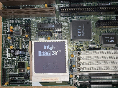
so graphics card, a single memory module (bank 0) and cpu.

OK as a last try, please remove also all 9 cache srams, maybe they are shortening something. Unlikely, but there were already cases, where bad srams spoiled the boot process.

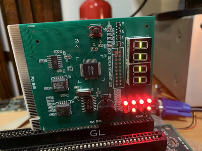
If that does not help either, next step would be a post card, I agree.
OK the bios could be empty, too, but that's not very likely. But OK, if you have a second 486 mainboard you could put the bios in from that, if it is socketed (even if completely different chipset and so on). Of course without bios nothing happens, also no beeping 😀 But I don't think it's the problem here.

Most probably the board has multiple defects.

Reply 53 of 99, by Parni

User metadata
Rank Member
Rank
Member

I tried to remove the cache and also tried with an other BIOS module from Shuttle HOT 419 (it has also a OpTi 895 chipset) but it didn't work.
Maybe i'll just scrap this mobo?

Reply 54 of 99, by computerguy08

User metadata
Rank Member
Rank
Member
Parni wrote on 2020-05-04, 14:58:

I tried to remove the cache and also tried with an other BIOS module from Shuttle HOT 419 (it has also a OpTi 895 chipset) but it didn't work.
Maybe i'll just scrap this mobo?

You shouldn't scrap it, 486s are not that common to find. Put it in storage, it will find its use one day.

If you need a DOS gaming PC, get a Pentium. I've played with my 486 recently (the J-403TG with Opti chipset), and I remembered what a nightmare it was. Frequent POST issues (completely dead, just like yours), VLB compatibility issues, etc. I keep it around though, because it's a unique piece of history in home computing.

Reply 55 of 99, by Parni

User metadata
Rank Member
Rank
Member
computerguy08 wrote on 2020-05-05, 06:34:
Parni wrote on 2020-05-04, 14:58:

I tried to remove the cache and also tried with an other BIOS module from Shuttle HOT 419 (it has also a OpTi 895 chipset) but it didn't work.
Maybe i'll just scrap this mobo?

You shouldn't scrap it, 486s are not that common to find. Put it in storage, it will find its use one day.

If you need a DOS gaming PC, get a Pentium. I've played with my 486 recently (the J-403TG with Opti chipset), and I remembered what a nightmare it was. Frequent POST issues (completely dead, just like yours), VLB compatibility issues, etc. I keep it around though, because it's a unique piece of history in home computing.

OK, i will put it in storage. I still could try the POST CARD at some stage, would this be a good choice for it? https://www.ebay.com/itm/PC-Motherboard-Analy … EkAAOSwa2lZguL3

Reply 56 of 99, by computerguy08

User metadata
Rank Member
Rank
Member
Parni wrote on 2020-05-05, 13:29:

OK, i will put it in storage. I still could try the POST CARD at some stage, would this be a good choice for it? https://www.ebay.com/itm/PC-Motherboard-Analy … EkAAOSwa2lZguL3

Yes, it will work fine.

Reply 57 of 99, by Parni

User metadata
Rank Member
Rank
Member

Hello Gents,

OK, so I got myself a POST card, this is the result. It wont show any codes, i tested with other mobos and the post card is working. Any tips?

postcard.jpg
Filename
postcard.jpg
File size
208.69 KiB
Views
1166 views
File license
CC-BY-4.0

Reply 58 of 99, by computerguy08

User metadata
Rank Member
Rank
Member

You could try to flash an Award BIOS on a 1Mb EEPROM (commonly found on Pentium boards) using Uniflash or AWDFLASH. I noticed that your board has a 32-pin socket.

Be sure to choose a BIOS compatible with the OPTi chipset. If the file is smaller than 256KB, just copy the contents inside until you get to 256KB with an hex editor.

Here is the BIOS image from my 486 board with the same 82C895 chipset.

Attachments

Reply 59 of 99, by Parni

User metadata
Rank Member
Rank
Member

Thanks! Now i'm just wondering what E/EEPROM programmer to buy 😀 any tips?

Also why do you recommend 32-pin in favour to the original 28-pin?

What come to the BIOS chips, could you also advice what are suitable 28 and 32-pin chips?