VOGONS


First post, by kool kitty89

User metadata
Rank Member
Rank
Member

Does anyone know what might cause the -12V line on an AT form factor motherboard to short to ground?

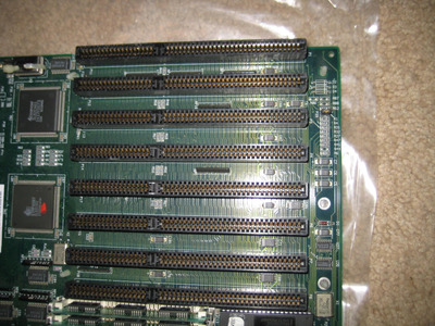
This is a 486 chipset board without onboard I/O or sound (it's a Symphony chipset board with 386 and 486 sockets) and I don't think any of the onboard logic makes use of -12v signaling or reference voltages.

I had it working with a few different 486SX and DX chips, 486DLC, AM386DXL-40 (which it came with), and an Intel 386DX-25. (the latter running at 33 MHz using a 66 MHz oscillator I swapped in for the 80 MHz one it came with)

I'd had it idling on 3Dbench for a while with the 386 and left the room to check on something else and found it turned off.
I thought I'd just forgotten I'd shut it off before I left and swapped in a i386DX-33 IV and it wouldn't power on.

I realized the PSU was staying off with either position of the switch, so I unplugged everything, then tried the power supply again and its fan spun up fine, tried a 90mm fan and it powered that on fine too. Tried plugging it into the board again and it stayed off. (the internal breaker popped, and reset after unplugging the PSU from the board and AC power for several seconds)

I tried the PSU in another board and that worked fine, then tried just the P9 half of the AT connector (5V, -5V, gnd only) and the PSU powered up fine, then P8 and it stayed off again.

So I probed the P8 side of the connector on the board using a multimeter in resistance mode and the +12, key (+5V), and power good lines all showed high resistance values as expected but the -12V line read only 0.9 ohms, so it seems like there's a short there.

I don't see any obvious damage on the board and I didn't notice any foreign objects in the ISA slots (or any flecks of scraped gold contact plating) that might short the -12v line there and no burnt or blown capacitors or diodes around the ISA slots or elsewhere.

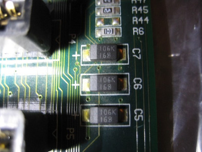
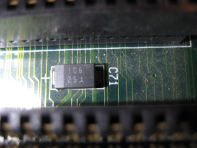
I'm currently thinking it may be a capacitor that failed shorted and the PSU halted things before it could actually pop or burn. If it was one of the tantalum caps it obviously would've failed more dramatically if allowed to and had it been on the +5V line the PSU might have passed enough current to allow that (it's done that on an 8088 board before) but the -12V line has a low current threshold that may be preventing that.

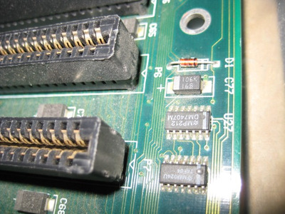
All the tanalum caps are black, rectangular surface mounted things so also might not show partial burning (but there was no odor and no change to the white polarity markings on them) and I didn't see any discoloration to the ceramic caps around, even the tiny surface mounted ones. (though some of the tiny SMDs I was looking at were probably resistors)

To be clear: the board was unpopulated when I did the power on testing, so no cards in the ISA slots could be the source of the short. I don't think the video card makes use of it anyway, but the Vibra 16S I have does have the -12V pin connected and the multi-IO card I had hooked to a CF adapter does have it for the RS-232 ports (which were unused during these tests).

Reply 1 of 10, by quicknick

User metadata
Rank Oldbie
Rank
Oldbie

One of the caps is shorted, most certainly. They don't always explode or go up in flames. I guess it depends on the amperage available to the respective rail, and the internal resistance after the short (close to zero ohm should be better than, say, 1 or 2 ohms, because of lower dissipation).

Reply 2 of 10, by Horun

User metadata
Rank l33t++
Rank
l33t++

I agree quicknick. If it were me I would pull the -12v out of a PSU P8 connector (with the sound card removed) and see if the board boots. It should since it does not have onboard I/O but never know. Just a thought.

Hate posting a reply and then have to edit it because it made no sense 😁 First computer was an IBM 3270 workstation with CGA monitor. Stuff: https://archive.org/details/@horun

Reply 3 of 10, by pentiumspeed

User metadata
Rank l33t
Rank
l33t

There is not many capacitors on the -12V circuit, You could pull out one pin of capacitor at a time with soldering iron till found shorted capacitor?

Cheers,

Great Northern aka Canada.

Reply 4 of 10, by kool kitty89

User metadata
Rank Member
Rank
Member

As I mentioned, the power supply I'm using has an internal breaker and it's fairly sensitive, especially to short circuits. So it definitely seems possible that there could've been a more dramatic failure with another PSU.

I wrote a bit about it here and the model:
AT (and ATX) Power supplies with integrated circuit breakers.

EMACS model ET2-4200UF
200W

.5A rated for both -5 and -12V rails

I assume it's a fairly high-end old power supply, maybe intended for server use, or just a high-end AT workstation power supply. It uses a built-in rocker switch and has no remote AT power switch cable routing, so would make sense for a server. (or maybe intended for a Baby-XT/AT clone cases without remote power switches)

I don't really want to hack up the cable on that PSU since it's been pretty dependable so far and it's in nice shape.
I'd rather do that to an ATX to AT adapter dongle if I had do go that route for testing. Or even using an adapter with a newer ATX PSU that lacks a -12V rail entirely. (though I think it's just the -5V line that got removed from the ATX spec, or at least it got removed first)

I could try isolating the -12V pin on the motherboard's connector with some tape or just bending it slightly out of the way, though I don't want to break the pin off by going too far with that. The tape might not work, but worst case would be getting it stuck in the PSU's socket ... which I'm not sure is any better than cutting and later resoldering that wire.

As for the caps:

They're all rectangular plastic block surface-mount capacitors.

I thought they were probably tantalum in spite of being black, but they could be aluminum polymer solid electrolytic capacitors. I don't think the insulator color always indicates the type, though.

They're all polar and I believe they're all the same capacitance rating with 106 or 106k printed, and I think 16 and 25V ratings, but some other symbol than V is used. One looks sort of like a lowercase delta ( δ ) and the other looks like kanji or some other japanese/chinese alphabet character but maybe both are the latter.

16 and 25V make sense for the typical margin for error above the required (12V) potential difference. (and any circuits that might pull +5 or +12V along with the negative would presumably be pulling current in series with additional capacitors on those rails)

I think all those caps have j-leads on them, so even if I could get in there and desolder just one of the poles, there's a good chance the other solder joint would crack (or worse, lift the pad/trace) if I tried to pry it up.

If they had the other type (is it L-lead or gull-wing or something?) with flat-outward facing leads like some other surface mounted parts use (and most can-type SMD electrolytic caps) I could probably lift it safely, but they really look like J-lead parts.

Maybe if too much solder hasn't flowed into the bend of the J-lead it could still be unbent slightly.

I'd still be worried about bumping one of the ISA slots with the soldering iron and melting/damaging it, though, especially if I had to do that with a dozen or so capacitors.

I guess I could start with the ones around the slot the sound card was in. Presuming it uses the -12V rail in the amp circuitry that probably would be the only load on that rail, but it might not have been a capacitor under load that failed:
If there was a flaw in one of the capacitors or it was previously under enough stress to be damaged, I'd think just being powered on, idle, for long enough could cause further deterioration and failure.

Attachments

Reply 5 of 10, by kool kitty89

User metadata
Rank Member
Rank
Member

I also double-checked the open-circuit voltage output of that PSU (something I did before I started using it about 6 months ago).

The +5V lines all read between 5.20 and 5.24 (most settle in at 5.23 if I wait for a bit, but the power good line appears to settle at 5.20).

+12V = 11.70V

-5V = -4.55V

-12V = -11.35V

I recall these to be pretty much the same as I measured before, though I have another multimeter that tends to read slightly lower than this one and I'm not sure which is calibrated closer to true.

I compared with a newer ATX power supply (missing -5V) and it's pretty close to that, within .05V for most things, but the old EMACS PSU does read consistently lower.

I think it's a pretty cheap PSU, KENTEK 600W thing with only 22A on the 12V rail but 40 on the 5V one, so an oddball poor fit for newer systems (ie Athlon64 era stuff and onward) and potentially not fail-safe, but I got it as a cheap spare for older systems with well under half the rated power requirements and more 5V hungry. (though lack of -5V limits it somewhat on the ISA sound card end)

It gets 5.28V on the +5V line
+12.05V
-11.44V

no -5V line.

Edit:

also compared a little 90W FATX PSU and the values were a bit lower than the EMACs one and I realized it lacks a -5V line too, even though it appears to be an older one. I wonder if that contributed to problems with a Sound Blaster Pro 2.0 Apolloboy was using it with, though I swear it worked fine for the majority of things as it was. (with both an ATX 430HX based board and a Shuttle AV18 S370 board later on)
I'm pretty sure the issues he mentioned were actually specific to windows games and limitations/issues with 8-bit sound blaster compatibility, especially with stereo.

Oh ... wait, that also means this Vibra 16S was running fine with no -5V line as well, that or the ATX spec boards provide legacy -5V natively. (or the cards are using their onboard voltage regulators and the presence of the -5V ISA pin is redundant and/or it has something to do with the IDE CD-ROM interface that's not populated on either of these)

Actually, they each have a L7805 regulator onboard, so if those are being used to drop -12V down to -5V, that would put load on the -12V line. (I haven't followed the traces on the board, but I think it could have the external -5V and internal, regulated -5V lines wired in parallel and I'm not sure what that might do if there's a potential difference between the two -5V signals)

They also both look to have 9V linear regulators on there as well, and looking at pic of various non-PNP style Vibra 16S and 16C cards, they all seem to have some models of 7805 and 7809 or compatible regulators on board.

Given the regulated +5V signal already available on the ISA slot, I assume the 7805 is not there to provide +5V and is instead being used on the -12V rail.

The 9V regulator is probably used for +9V. I don't think there's normally need for -9V. Unless it's being used in series with the 5V one to spread the thermal load. (-12V being dropped to -9V by one regulator and then -9 to -5V in the second)
Both just have their heatspreaders screwed to the card's surface, so can't be expected to dissipate much heat.

Reply 6 of 10, by kool kitty89

User metadata
Rank Member
Rank
Member

https://upload.wikimedia.org/wikipedia/common … us_pins.svg.png

I checked again and pins B5 and B6 are absent, but B7 is there. So there's no connection to the -5V rail on the board, but -12, +12V, and +5V are all there. (B7, B9, B3)

And I followed the traces to the 7805, it is going to +12V, and I now remember that audio amp circuits don't like ripple from switch-mode nonlinear power supplies and regulator ICs (or even just noise on a shared power line), so deriving its 5V signal through a linear regulator does make sense. (the same reason early model Sega Mega Drive/Genesis consoles have dedicated 7805s for the audio circuit)

The -12V line gets routed up to a pin on the wavetable header and to what I thought was a bipolar transistor.
cJ59BL
320L
79L05

But looking that up, 79L05 would be a negative 5 volt regulator.
So it is deriving -5V from -12V.

I think I was mistaken thinking that a positive VR used on a negative source voltage would work as a negative regulator, or maybe it can but isn't recommended. (the -12V signal would need to be fed to what's normally ground or 0V, and the source would be tied to ground)

So that's good to know, and I suppose useful info for others using these cards. I seem to recall a few threads on the issue that were inconclusive or assumed -5V was needed. (-12V does appear to be needed, though)

I also noticed the PC Speaker input header on this card that I've been neglecting to use. And come to think of it, the 2-pin header it uses would be easier to route to the 2-pin speaker heads on a lot of 286 boards. (or I guess baby AT boards aimed at the XT clone upgrade market)
I previously modded a 4-pin PC speaker plug inside a case for that sort of connector, but undid it when I swapped to a 486 board. (I'd used a short piece of wire threaded between the empty center 2 connector holes to one of the edge pins to make it work, and pulled that out to allow the 4-pin header to fit in again)

The 7809 routing was harder to work out so I'm not wasting more time on that right now, but I did confirm the sound circuit is using the -12V rail on this card.

I also did have the amplified speaker output plugged into my monitor's speakers at the time, and that would be the one with the heavier current draw. (I'm not sure the circuit would still be under significant load if there was nothing plugged into the audio out ports, but I think not, and presumably the line out would also use less)

I think I snapped a photo of the test bench set-up running while that sound card was in too, so I can poke around that slot first.

Reply 7 of 10, by kool kitty89

User metadata
Rank Member
Rank
Member

Ah, and 106 is a code corresponding to 10 micro-farad capacitors.

Now when I find the faulty one, I need to work out if I have to use tantalum caps or if ceramic or solid electrolytic aluminum ones would also be OK. Some people swap in wet electrolytic caps, but after some recent discussions I don't think I want to go that route (and 10 uf tantalum caps are pretty inexpensive and available at the moment). But I'm pretty sure ceramic and poly caps are safer in terms of failure mode and potentially less failure prone and have some performance advantages to tantalums.

I know tantalums are more reliable than wet electrolytics, but the failure mode is a lot worse and they're prone to run-away failures where poly caps tend to be self-healing and even wet electrolytic ones are to some extent: ie a small short in foil layers tends to quickly burn/oxidize into insulator material, so short of steam-pressure bulge/rupture/leak they can recover from that.

I remember Tiido mentioning swapping wet electrolytic for tantalum caps on some of his Sega hardware some years ago, and I'd think poly caps would work the same there and maybe ceramic for some values.

But I was looking at these 2 options in particular:
https://www.ebay.com/itm/50-V-106-10-uF-10-pc … SA/303531468050

https://www.ebay.com/itm/10pcs-NIC-10uF-35v-1 … or/143602319481

And I might as well buy a lot of capacitors as I don't have them on hand right now and have some other projects that could use them, including old video came console boards. (I'm pretty sure a lot of them also use 10 uf specifically, but I an assortment would be useful)

I'm confortable replacing SMDs with through-hole components and did that years ago with a Sega Game Gear as well as some video cards with falling-off caps. (bend/loop the ends of the leads, tin them, and solder to the surface pads)

It might be worth replacing all of them to avoid similar (or worse) failures. And replacing all of them wouldn't be much more work than the desolder-and-test-each-one approach.

The easy/lazy route would be just to find the bad one, desolder it and not have -12V on one of the slots. (at least for the short-term)

Reply 8 of 10, by kool kitty89

User metadata
Rank Member
Rank
Member

I thought i'd found the bad one, but it seems the board has the ISA slot power lines wired in 2 separate parallel runs, staggered on even and odd slots, so probing with all the caps still soldered on made it look like every other slot had a shorted one.

I started with the one closest to the power socket, which turned out to be one of the 25V ones. It turns out the J-lead SMD parts do lift off and unhinge at the J-bend, but it did so by suddenly popping up and nearly bending over flat, so I ended up desoldering it entirely.

It turned out to still be good (resistance in the M-Ohm range) but the un-bent lead ended up snapping off when I pressed it back into shape, so I'll have to replace that one two.

Second time was the charm and it was the one right next to the sound card (though given they appear to be wired in parallel like that, I'd think one of the other 16V rated ones would be similarly likely to fail).

Any replacements I use are probably going to be 25+ volts. (those ebay listings I'm looking at are 50V for the ceramics and 35 for the tantalums)

Except I'm not sure if polar caps are necessary here or if nonpolar ceramics are OK.

It is kind of weird how nearly everything (pretty much aside from socket mounts and resistor arrays) on this board is surface-mount for something from 1992. Lots of tiny SMD resistors, caps, TSOP chips, and QFPs. (the latter was common for the chipset, though)

It's more like some video game consoles from about the same time or kind of like the Batman Pentium motherboards from '93.

This is obviously not an Intel-centric board though given the 386/DLC + 387 sockets, though I guess the presence of both a 486 DX/SX and i487 socket is intel-ish, or just covering all bases. (it seems more common for boards to just have jumpers to set the same socket to 486SX, DX, or 487, though) Not sure if the 387 socket can be used with 486SX chips either, doesn't seem to do so for Intel or AMD SXs, but maybe for Cyrix ones given 486S and SXL chips from Cyrix/Ti were intended to be mated to '87DLC style copros. (usually via nesting PGA socket adapters, but I've seen some boards with spots for surface mount QFP-80 487DLC chips and it would make sense to do the same for socketed FPUs)

It'd make sense if Intel and AMD 486SXs specifically didn't support external co-pros since Intel wanted to promote the 486SX and their 487SX upgrade chips vs AMD who'd just want to sell 486DXs to that market sector and wasn't selling 387-socket co-pros of their own (I think). Vs Cyrix (and partners) who'd benefit more from supporting upgrade options, potentially even after their 486DX was on the market, but certainly back when they were only selling FPU-less PGA-168 chips.

Those passthrough adapter 487DLC things were also necessary for typical 386/486 boards that shared the 387 and 486 sockets. (I suppose a riser socket would leave room for a 387/487DLC under a 486S, but I have no idea if any boards supported that sort of pairing)

Reply 9 of 10, by kool kitty89

User metadata
Rank Member
Rank
Member

Oh, and the board appears to be working fine again. The remaining filtered -12V enabled ISA slots also seem to work fine, but I'll need to re-cap the missing spots at some point. I'm also avoiding using the amplified speaker out on any sound cards for now.

386, 486DLC, 387, 486DX sockets all working, board level cache is fine too up to the 40 MHz (80 MHz oscillator) it came with stock. No new odd behavior.

There's some existing odd behavior was the turbo switch functionality actually making the system faster when no cache was present: ie turbo-jumpered on has faster DRAM speed and higher system performance than jumpered off and cache(s) turned off (cache also appears to be auto-disabled when jumpered on, though I did see very slightly higher figures for Landmark when cache was switched on in the BIOS, oddly). This behavior may not hold true for 486SX/DX CPUs, but definitely for the 386 socketed chips.

The only other weird things seem to be that Speedsys hangs with 486DLCs at any speed I've tried even though they're actually more stable in this board than the 386DX40s I've tried for pretty much all other programs, and the BIOS's internal CPU cache switch doesn't seem to change benchmark results for the DLC40 so it may not be working . (not sure if the cache is stuck on or off) And both cachecheck and RAMbench.com don't have enough granularity within the first 1kB to make the L1 Cyrix cache performance obvious. (or it just may be stuck off since I recall cachecheck showing a difference in the 1kB range when I tried the 486DLC in my OPTi 495SX based 3486 board)
I'll have to try using a Cyrix register setting utility later on. (the board-level cache on this symphony board is super fast, though, so probably wouldn't impact performance much: maybe more so if the Cyrix cache was switched into set-associative mode rather than direct-mapped: assuming the board-level cache is direct-mapped)

The turbo header is also labeled 'speed' instead of turbo, but has the normal Turbo LED behavior where jumpered = off and open = on. (a PCChips M396F 386SX40 board I have needs the turbo jumper closed to run in fast mode: seems to just control wait states in that case)

Reply 10 of 10, by kool kitty89

User metadata
Rank Member
Rank
Member

I got a bit mixed up over filtering vs decoupling caps on DC supply lines, but I'm now sure these must be decoupling caps.

see:
Re: 486 Tower find -- VLB Card suggestions

they must be decoupling caps as there's live 12V (or -12V) power going across the two contact pads for the capacitors. […]
Show full quote

they must be decoupling caps as there's live 12V (or -12V) power going across the two contact pads for the capacitors.

If they were filtering caps, they should be open-circuit unless a card in one of the ISA slots is present, closing the circuit.

And if a filtering cap failed short it wouldn't have been causing the problems I had (short-circuit on the -12V pin of the AT power socket/connector) where a shorted decoupling capacitor would be shorting between live and ground.

So these are larger(er) value decoupling capacitors doing part of the same job that filtering caps do (smoothing out AC signal noise in the DC supply line).

That also means the -12V lines on all ISA slots are still live, but there's now fewer decoupling caps running in parallel to suppress ripple/noise.

So I also shouldn't worry too much about which slot I put the sound card (or other -12V requiring card) but the supply voltage may still be somewhat cleaner next to the still-present caps and on the other bank of ISA slots. (again, those decoupling caps appear to be arranged as two separate banks of caps isolated from eachother, each bank wiring all the caps in parallel so all the ones on the same bank as that shorted one appeared shorted but the others did not: I assume there's doides or something allowing that isolation of that other bank)

Also, probing the -12V lines on the board side with the power on got me -12.21V rather than that -11.35V straight off the power supply, so there's probably quite a lot of AC ripple/noise on that line that's getting filtered out by the board.

I also checked the 5V line and it's 5.05V on the board side at the ISA slot and on the CPU socket, so also much closer to 5.00V than the open-circuit values I took from the PSU. (though I've got some 7805 regulated game consoles that are stuck with closer to 4.9V on their 5V supply lines and not due to weak input power supplies: ie the input power was all reading well. well above the 7V minimum threshold, in the 9-10V range depending on AC addapter used)