Reply 100 of 106, by GEOCE
Rank
Newbie
I no longer have the DX4 on that board. From what I see in the video, I would try what happens only with the graphics card, the rest of the cards out, since the next step to the memory count I think is to initialize the expansion cards.
But, even if it worked for me at 5V without problems, nothing guarantees that all processors will do it.
How can i know if the micro goes to 75mhz or 100mhz? Can i see on the micro?
I have a question, I've decided to do the mod, I have version 1 of the board and I only have 4 voltages to change. In the manual I've seen from Chicony version 2, there are 5 voltages. In the manual, I read about pins 9-10 for 3.3v, but in version 1 I don't have that option; I only have pins 7-8.
When doing the mod, how can I achieve the 3.3v I need for the 486DX4-100mhz? I'm very new to this, so please forgive me if the question is stupid xD.
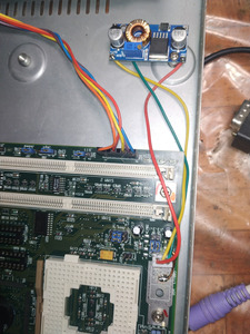
From my experience I decided that it is much better to do it in another way using a modern DC-DC step down with adjustable output voltage, I used one based on an XL4005. These modules are very cheap, cheaper even than the MIC and the resistors, the voltage output will surely be much more stable and cleaner than with the original system from 30 years ago.
I did it on a Packard bell 486 board that also didn't have the 3.3v circuit components, and it was faster and easier. My 486DX4 is now on that board and with the voltage reduced to 2.7v without any stability problems and cold as ice.
I'm very new to this, how could I do that on my motherboard? I just don't know where to start with that
.
My English isn't very good and it scares me a bit to explain what to do, anyway if you don't have soldering practice and some basic knowledge, I wouldn't recommend doing such a modification on a motherboard. I assume that you have some basic knowledge of soldering, use of the multimeter and interpretation of electronic schematics if you want to carry out this modification in one way or another.
Anyway, this video ( https://www.youtube.com/watch?v=3PNN60Wdj0E ) could be useful for you to learn how a simple step down works and the concept of powering the processor using it.
At the end of the day, the processor doesn't care where it gets the power from, just that there is 3.3v on the VCC pins and enough current to work.
Basically it is about connecting the positive input of the step down to what would be the input pin of the voltage regulator, that is to say at 5V, the negative input of the step down to any negative point and the positive output of the step down to what would be the VOUT of the voltage regulator that goes to the VCC pins of the CPU.
Going through this thread, there are quite a few photografs and diagrams, more good or bad that should be quite explanatory.