VOGONS


First post, by Uroshnor

User metadata
Rank Newbie
Rank
Newbie

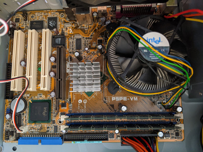
I recently bought an Asus P5PE-VM motherboard on eBay, and a new InWin EM013 case to put it in (since that was one of the few micro-ATX cases still available with both external 5.25" and external 3.5" drive bays).

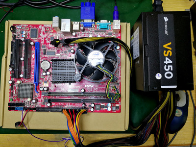
The motherboard came with a CPU and RAM pre-installed, so today, in order to test it, I attached the included stock CPU cooler, plugged it in, and then plugged the motherboard into the case's included power supply and chassis fan.

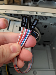
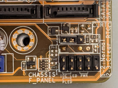
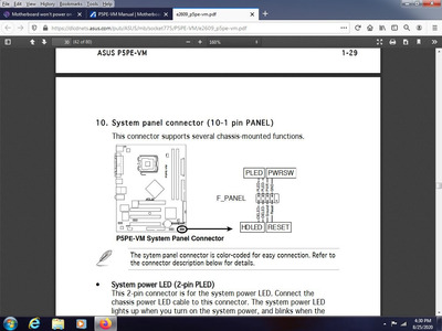
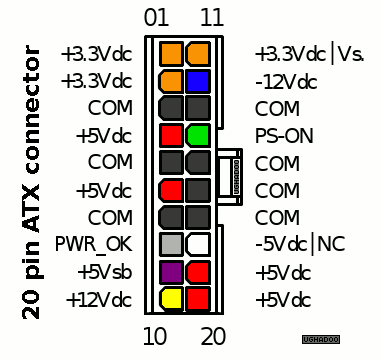
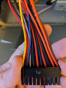
The motherboard doesn't have its own power button, so I figured I'd need to plug in the front panel connectors as well, in order to use the case's power button. Unfortunately, the case didn’t come with any documentation, nor is there any available on InWin's website, and as far as I can tell, there’s no indication on the connectors themselves as to which pin is which. I’ve plugged the power and reset button connectors into the motherboard in every configuration I can think of, based on the diagram in the motherboard's manual, and none of them have allowed me to successfully power it on.

The power LED on the motherboard lights up when I plug in the power supply, so I know it’s getting power, but absolutely nothing happens when I press the power button. The fans don’t even spin up or anything.

Unfortunately, I don’t have any spare cases, power supplies, or motherboards I can use to test the various components.

Can any of you help me out at all? Do you happen to know the correct orientation for the connectors, or a way of finding out? Or alternatively, can you spot anything I’ve done wrong, or anything I forgot to do, that would prevent the motherboard from powering on?

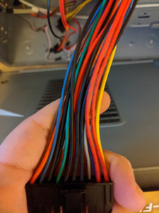
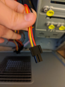
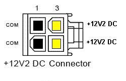
Photos of the motherboard and connectors attached for reference.

Attachments

Reply 1 of 47, by debs3759

User metadata
Rank Oldbie
Rank
Oldbie

The cable from the power switch on the case plugs into the two pins where it is marked PWR on the board.

See my graphics card database at www.gpuzoo.com
Constantly being worked on. Feel free to message me with any corrections or details of cards you would like me to research and add.

Reply 2 of 47, by quicknick

User metadata
Rank Oldbie
Rank
Oldbie
Uroshnor wrote on 2020-08-25, 23:08:

Or alternatively, can you spot anything I’ve done wrong, or anything I forgot to do, that would prevent the motherboard from powering on?

Yeah, never power a motherboard that's just inserted into a case but not secured with any screws. Hopefully nothing bad happened. Fit at least 3-4 screws, or better yet, take it away from the case and test everything on a "bench".

Reply 3 of 47, by Repo Man11

User metadata
Rank Oldbie
Rank
Oldbie

The first thing you can try is to ground the power on posts with something to see if it powers on that way - I usually use a philips screw driver that's just the right size to touch the two prongs and nothing else. If nothing happens when you do that, I'd try removing the board from the case, put it on top of an anti static bag on a counter and use one stick of RAM, a known good video card (PCI preferably) and connect the PSU and try again. This eliminates any possibility that the board is going to ground somewhere it isn't supposed to.

"I'd rather be rich than stupid" - Jack Handey

Reply 4 of 47, by Horun

User metadata
Rank l33t++
Rank
l33t++

Do the above and screw the board down, before you do make sure there are no case back panel parts that could short against the back of the board. Next: ALWAYS check the manual before relying on any silkscreen on the board as it could be confusing. According to manual the Power On is in top row, does not matter which way you hook it to the case power button (is Labeled Power SW on the case leads and there is no + or -). See the picture below, page 1-30, for the documented front panel connector.

You really should do as Repo said and "breadboard" test it out of the case, is what all the techs I know do with every motherboard before trying to mount in a case.

Repo Man11 wrote on 2020-08-25, 23:21:

I'd try removing the board from the case, put it on top of an anti static bag on a counter and use one stick of RAM, a known good video card (PCI preferably) and connect the PSU and try again. This eliminates any possibility that the board...

Attachments

  • Image2.jpg
    Filename
    Image2.jpg
    File size
    137.95 KiB
    Views
    1069 views
    File license
    Fair use/fair dealing exception

Hate posting a reply and then have to edit it because it made no sense 😁 First computer was an IBM 3270 workstation with CGA monitor. Stuff: https://archive.org/details/@horun

Reply 5 of 47, by Uroshnor

User metadata
Rank Newbie
Rank
Newbie
Horun wrote on 2020-08-25, 23:39:

Do the above and screw the board down, before you do make sure there are no case back panel parts that could short against the back of the board. Next: ALWAYS check the manual before relying on any silkscreen on the board as it could be confusing. According to manual the Power On is in top row, does not matter which way you hook it to the case power button (is Labeled Power SW on the case leads and there is no + or -). See the picture below, page 1-30, for the documented front panel connector.

You really should do as Repo said and "breadboard" test it out of the case, is what all the techs I know do.....

Repo Man11 wrote on 2020-08-25, 23:21:

I'd try removing the board from the case, put it on top of an anti static bag on a counter and use one stick of RAM, a known good video card (PCI preferably) and connect the PSU and try again. This eliminates any possibility that the board...

I did see that in the manual. It doesn't seem to work either way.

I had originally intended to test it out of the case, but the power supply's cables are too short to reach that far, and as I said, I don't have another power supply I can use.

Thanks for the advice to screw it down and check for back panel shorts.

Last edited by Uroshnor on 2020-08-26, 00:21. Edited 1 time in total.

Reply 6 of 47, by Uroshnor

User metadata
Rank Newbie
Rank
Newbie

Ok, I've tried it screwed down (fwiw, even before I did that, I was making sure the screw holes were aligned before plugging it into power, so I strongly doubt it was shorting on the case), I've tried it outside the case on an antistatic bag (I found a way to make the power cables reach), I've tried it with a single stick of RAM, and I've tried shorting the power button pins with a screwdriver like RepoMan11 suggested.

Nothing worked. Every time, the power LED lit up as soon as it was plugged into power, but nothing else happened. The fans didn't spin up, the internal speaker didn't beep, nothing.

Reply 7 of 47, by Horun

User metadata
Rank l33t++
Rank
l33t++

What brand and Model is the PSU ? May sound far-fetched but have seen some newer ATX PSU not power up on an older board, ususally is visa-versa but not always. Has to do with the ATX12 and EPS12 specs the board has and what the PSU is and expects to see on the board. The LED turning on most likely would be from the +5VSB (all ATX have it) not the actual PSU mains being active.
Glad to hear you pulled the board back out, wish you had another ATX psu to try. I assume the Ebay seller said it worked, can you post the last part of the ebay listing (just the 12 digit number is fine, like: 184318667740) ? Thanks !

Hate posting a reply and then have to edit it because it made no sense 😁 First computer was an IBM 3270 workstation with CGA monitor. Stuff: https://archive.org/details/@horun

Reply 8 of 47, by kalohimal

User metadata
Rank Member
Rank
Member

The PSU cables color coding looks very unusual. The 4-pin CPU power connector are usually 2 yellow and 2 black wires. On the 20-pin atx connector, the 2 wires on the extreme left should be orange which supply 3.3V (they look red, colour shift in the photo perhaps?)

5mXA6.png
Filename
5mXA6.png
File size
8.91 KiB
Views
1013 views
File license
Fair use/fair dealing exception

Try shorting the top 2 pins next to the missing one using a screwdriver, as shown by Horun. If it still won't start, you could disconnect the 4-pin CPU power connector and try again with only the 20-pin connector plugged in. If the fan spins up it means there are faults in the VRM. If not, it could mean there are shorts elsewhere on the board (the green LED could still light up in this case as most PSU do not have short circuit protection on the 5V standby rail, and also the short might be on the main rails).

Last edited by kalohimal on 2020-08-26, 02:21. Edited 1 time in total.

Slow down your CPU with CPUSPD for DOS retro gaming.

Reply 9 of 47, by Uroshnor

User metadata
Rank Newbie
Rank
Newbie
the OUtSIDer wrote on 2020-08-26, 00:49:

Uroshnor Here's what works for me when powering up old hardware. 1. Don't assume that the marks for the power pins apply to the side of the board that they're printed on , the two pins on the other side of the connector do not have the room for easy labelling !?! 2. Do not assume that your connectors have the easiest format to use with your MOBO. #3. Take a Phillips screwdriver and ground yourself if worried about static and drag it across only 2 adjacent pins at a time, for a half to whole second. this should show you what pins are power on, and all others are generally for speaker, led- etc. and will not react. You should get a power on though.

Does anything happen do you get fans but no post beep? If you still get no power on , verify pwer supply (with a known working board), inspect capacitors and do a quick google search to be sure. Not all bad caps are easy to spot. I googled Known issues and found a post in OVERCLOCKERS. problem with caps on this particular board, so that is a real possibility, but it's just as likley that there is oxidation on your power pins and therefore you can't activate them without a little finesse. P.S. If nobody said this before, its possible that the power plug would go either this way ll or this way = that is four combos for four pins (crazy I know) but still a possibility.

I haven't gotten the fans to run at all yet. I haven't noticed any bad caps, but I also haven't inspected them all that closely. I'll take a closer look later.

I haven't tried holding the screwdriver against the pins for more than a brief instant, so I'll also try holding it there for longer.

Unfortunately, the only known working motherboard I own is inside my main computer, and would be an *enormous* pain in the ass to extract. It also wouldn't fit inside this new case.

Reply 10 of 47, by Uroshnor

User metadata
Rank Newbie
Rank
Newbie
Horun wrote on 2020-08-26, 02:06:

What brand and Model is the PSU ? May sound far-fetched but have seen some newer ATX PSU not power up on an older board, ususally is visa-versa but not always. Has to do with the ATX12 and EPS12 specs the board has and what the PSU is and expects to see on the board. The LED turning on most likely would be from the +5VSB (all ATX have it) not the actual PSU mains being active.
Glad to hear you pulled the board back out, wish you had another ATX psu to try. I assume the Ebay seller said it worked, can you post the last part of the ebay listing (just the 12 digit number is fine, like: 184318667740) ? Thanks !

Photo of power supply attached. It's just the one that came with the case.

I was actually thinking of buying an inexpensive power supply just to use specifically for bench testing in the future. Any recommendations?

Yes, the seller claimed it was “Tested working, Pulled from a working computer.”. The number at the end of the URL is 264815032749.

Attachments

Reply 11 of 47, by kalohimal

User metadata
Rank Member
Rank
Member

Usually I'd test out boards on a bench like this before putting it into a case, as it's much easier to work with. The PSU can be taken out from the case quite easily, there are only 4 screws securing it at the back.

IMG_20200826_102616.jpg
Filename
IMG_20200826_102616.jpg
File size
1.43 MiB
Views
1009 views
File license
Public domain

Slow down your CPU with CPUSPD for DOS retro gaming.

Reply 12 of 47, by Uroshnor

User metadata
Rank Newbie
Rank
Newbie
kalohimal wrote on 2020-08-26, 02:12:

The PSU cables color coding looks very unusual. The 4-pin CPU power connector are usually 2 yellow and 2 black wires. On the 20-pin atx connector, the 2 wires on the extreme left should be orange which supply 3.3V (they look red, colour shift in the photo perhaps?)

5mXA6.png

Try shorting the top 2 pins next to the missing one using a screwdriver, as shown by Horun. If it still won't start, you could disconnect the 4-pin CPU power connector and try again with only the 20-pin connector plugged in. If the fan spins up it means there are faults in the VRM. If not, it could mean there are shorts elsewhere on the board (the green LED could still light up in this case as most PSU do not have short circuit protection on the 5V standby rail, and also the short might be on the main rails).

Photos attached for a closer look at the power connectors. Those wires look kind of orangeish-red in person; hard to tell what color they're actually supposed to be.

I'll try it with the 4-pin connector unplugged next time I have the energy to test it. Thanks for the suggestion!

Attachments

Reply 13 of 47, by kalohimal

User metadata
Rank Member
Rank
Member

Yeah this doesn't look right. It should be yellow, yellow, black, black.

4-pin Connector.jpg
Filename
4-pin Connector.jpg
File size
984.71 KiB
Views
997 views
File license
Fair use/fair dealing exception

If a multimeter is available I would measure the voltage on the pins. It should be like this:

ATX-12v.jpg
Filename
ATX-12v.jpg
File size
7.71 KiB
Views
997 views
File license
Fair use/fair dealing exception

If there are indeed other voltages (can't tell the color, red? or orange?) then it would cause the rail to short to ground.

Slow down your CPU with CPUSPD for DOS retro gaming.

Reply 14 of 47, by kalohimal

User metadata
Rank Member
Rank
Member

Wait a minute, this is not the 12V 4-pin connector. It is the extension to the 20-pin atx connector which could be attached to the side of the 20-pin to make it 24-pin. You should have another cable that is 12V 4-pin, with the colors as described above.

4-pin Connector.jpg
Filename
4-pin Connector.jpg
File size
984.71 KiB
Views
995 views
File license
Fair use/fair dealing exception

Slow down your CPU with CPUSPD for DOS retro gaming.

Reply 15 of 47, by Horun

User metadata
Rank l33t++
Rank
l33t++

Yeah something does not look right with that 4Pin connector. Doesn't the PSU have some labels on the connectors ?

Hate posting a reply and then have to edit it because it made no sense 😁 First computer was an IBM 3270 workstation with CGA monitor. Stuff: https://archive.org/details/@horun

Reply 16 of 47, by Uroshnor

User metadata
Rank Newbie
Rank
Newbie
kalohimal wrote on 2020-08-26, 02:51:

Wait a minute, this is not the 12V 4-pin connector. It is the extension to the 20-pin atx connector which could be attached to the side of the 20-pin to make it 24-pin. You should have another cable that is 12V 4-pin, with the colors as described above.

4-pin Connector.jpg

This power supply has two connectors with only yellow and black cables. One is 6-pin, the other is 8-pin. No 4-pin. Do I need to get a different power supply?

Reply 17 of 47, by Uroshnor

User metadata
Rank Newbie
Rank
Newbie
Horun wrote on 2020-08-26, 03:04:

Yeah something does not look right with that 4Pin connector. Doesn't the PSU have some labels on the connectors ?

No proper, unambiguous labels, just stuff like "P1", as seen on the photo of the 20-pin connector.

Reply 19 of 47, by kalohimal

User metadata
Rank Member
Rank
Member

Yeah check if the 8-pin connector could be split, normally they do. If not, you can still plug in just 4 pins, observing proper orientation of course (the holes are keyed, they should not go in at the wrong orientation unless forced).

Slow down your CPU with CPUSPD for DOS retro gaming.