VOGONS


First post, by RichB93

User metadata
Rank Member
Rank
Member

Hi all,

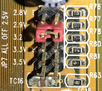
I have a couple of Socket 7 boards and I'd like to know where to start with regards to modifying the CPU voltage selection jumpers to use a Tillamook CPU on both of them. One board is a PC Chips M550 which goes as low as 2.5v with no jumpers installed, all the way up to 3.5v using a single jumper

PC Chips M550 Motherboard CPU voltage jumpers.jpg
Filename
PC Chips M550 Motherboard CPU voltage jumpers.jpg
File size
572.62 KiB
Views
1031 views
File license
Public domain

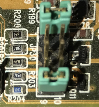
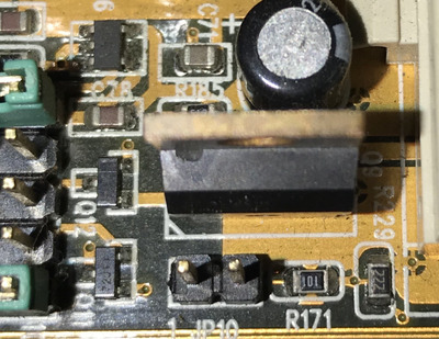
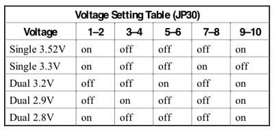
The second board is a Soyo SY-5BT which uses a more confusing dual jumper configuration to offer voltages from 2.8v to 3.5v. This is unfortunately the earlier revision 1 board which doesn't have the additional jumpers which allow a 2.2v selection, close enough to the 1.9v spec of the Tillamook for me to not worry about having to modify anything. I have however noticed a JP10 jumper nearby which looks somewhat related and is suspiciously not documented in the manual (or even shown on the board diagram).

Soyo SY-5BT Motherboard CPU voltage jumpers.jpg
Filename
Soyo SY-5BT Motherboard CPU voltage jumpers.jpg
File size
405.2 KiB
Views
1031 views
File license
Public domain
Soyo SY-5BT Motherboard JP10 jumper.jpg
Filename
Soyo SY-5BT Motherboard JP10 jumper.jpg
File size
565.42 KiB
Views
1031 views
File license
Public domain
Soyo SY-5BT Motherboard CPU voltage settings.png
Filename
Soyo SY-5BT Motherboard CPU voltage settings.png
File size
33.14 KiB
Views
1031 views
File comment
Taken from the SOYO SY-5BT rev 1.1 manual
File license
Fair use/fair dealing exception

As I understand it, Tillamook CPUs all but work now on many S7 boards (these are both 430TX chipset) with full L2 cache support, thanks to some easily done soldering modifications to force the cache enabled and also set the 4x multiplier. I'm happy to do this work, but obviously before I buy some chips and do so, I'd like to get the CPU voltage down on these boards.

I can see varying resistors next to each of the jumpers, so I assume it's the case of working out the correct value.

Can anyone here help?

Reply 1 of 10, by cyclone3d

User metadata
Rank l33t++
Rank
l33t++

What voltage do you get with all the jumpers off on the SOYO?

From that chart, it looks to me like there would also be another jumper that chooses between single and dual voltage.

I bet you get 2.2 or 2.1v with all jumpers off.

Yamaha modified setupds and drivers
Yamaha XG repository
YMF7x4 Guide
Aopen AW744L II SB-LINK

Reply 2 of 10, by RichB93

User metadata
Rank Member
Rank
Member
cyclone3d wrote on 2020-10-04, 05:00:

What voltage do you get with all the jumpers off on the SOYO?

From that chart, it looks to me like there would also be another jumper that chooses between single and dual voltage.

I bet you get 2.2 or 2.1v with all jumpers off.

Where would I measure this? Need to get myself another multimeter as mines kaput, but I can grab one.

Reply 3 of 10, by RichB93

User metadata
Rank Member
Rank
Member

Got a multimeter and found where to measure the voltage on the PC Chips board. Not the same board but based my experiments on instructions from here: http://th2chips.freeservers.com/m565/vmod.html. With this, I was able to get the board down to 2.2v by removing the resistor at R63 (marked 2001) and installing jumpers on both D&E. I've ordered a 266 MHz Tillamook CPU so hopefully I should be able to get it up and running on this board- 2.2v is still .3v over the spec, but should be okay I'm sure, seeing how people have pushed these chips when clocking them on SS7 boards.

Fingers crossed!

Reply 4 of 10, by RichB93

User metadata
Rank Member
Rank
Member

So just an update to this - I received the CPU and it posted @ 2.2v on the M550 board. But I can't get it to run at 4x multi, and the internal cache won't work either (but the external does!) - I wonder if this is due to the BIOS not having Microcode for the chip.

The SOYO board works absolutely fine with the chip however; full 4x multi, cache fully working - it's appreciably faster than the 233MHz chip that was in there. The problem is however that the stupid 'auto voltage' function of the board means that the CPU operates only at 3.3 or 3.5v... way too high for comfort. With that being said however, the chip doesn't even start to get warm.

Does anyone have any ideas as to how I could modify the SOYO board to give me better control over the voltage? Whilst the chip isn't running hot, I don't want to fry it either!

Reply 5 of 10, by Tiido

User metadata
Rank l33t
Rank
l33t

Basically you desolder one of the resistors and install a potentiometer instead, with value that is in not far from the range seem on board already. You can then set an arbitrary voltage that you can set with just turn of the pot. This way is possible with most voltage regulators prior to introduction of Voltage ID pins. You'll want to consult datasheet of the regulator chip to find more info about how to go about it.

T-04YBSC, a new YMF71x based sound card & Official VOGONS thread about it
Newly made 4MB 60ns 30pin SIMMs ~
mida sa loed ? nagunii aru ei saa 😜

Reply 6 of 10, by debs3759

User metadata
Rank Oldbie
Rank
Oldbie

What sspec are the PGA Tillamook CPUs? I thought they only came as mobile modules, so would be interested to know more.

See my graphics card database at www.gpuzoo.com
Constantly being worked on. Feel free to message me with any corrections or details of cards you would like me to research and add.

Reply 7 of 10, by RichB93

User metadata
Rank Member
Rank
Member
debs3759 wrote on 2020-10-09, 20:53:

What sspec are the PGA Tillamook CPUs? I thought they only came as mobile modules, so would be interested to know more.

There are standard socket 7 chips which look like 233MMX chips. The seller on eBay said he pulled them from Compaq Presarios back in the day. There's a good few on eBay currently. Mine is a SL2Z4.

Tiido wrote on 2020-10-09, 20:35:

Basically you desolder one of the resistors and install a potentiometer instead, with value that is in not far from the range seem on board already. You can then set an arbitrary voltage that you can set with just turn of the pot. This way is possible with most voltage regulators prior to introduction of Voltage ID pins. You'll want to consult datasheet of the regulator chip to find more info about how to go about it.

Thanks Tiido; I've tried Googling various part numbers but I can't seem to find anything on the voltage regulator and I don't understand the auto voltage thing. As mentioned in the Tillamook thread however, the chip isn't getting warm running at the supposed 3.3v core that its currently using...

Reply 8 of 10, by debs3759

User metadata
Rank Oldbie
Rank
Oldbie

I didn't know SL2z4 were Tillamook. CPU-World says they are 2.5V, guess they are wrong.

See my graphics card database at www.gpuzoo.com
Constantly being worked on. Feel free to message me with any corrections or details of cards you would like me to research and add.

Reply 9 of 10, by RichB93

User metadata
Rank Member
Rank
Member
RichB93 wrote on 2020-10-09, 21:45:
There are standard socket 7 chips which look like 233MMX chips. The seller on eBay said he pulled them from Compaq Presarios ba […]
Show full quote
debs3759 wrote on 2020-10-09, 20:53:

What sspec are the PGA Tillamook CPUs? I thought they only came as mobile modules, so would be interested to know more.

There are standard socket 7 chips which look like 233MMX chips. The seller on eBay said he pulled them from Compaq Presarios back in the day. There's a good few on eBay currently. Mine is a SL2Z4.

Tiido wrote on 2020-10-09, 20:35:

Basically you desolder one of the resistors and install a potentiometer instead, with value that is in not far from the range seem on board already. You can then set an arbitrary voltage that you can set with just turn of the pot. This way is possible with most voltage regulators prior to introduction of Voltage ID pins. You'll want to consult datasheet of the regulator chip to find more info about how to go about it.

Thanks Tiido; I've tried Googling various part numbers but I can't seem to find anything on the voltage regulator and I don't understand the auto voltage thing. As mentioned in the Tillamook thread however, the chip isn't getting warm running at the supposed 3.3v core that its currently using...

Just want to clarify - no matter what jumper configurations are set up, I can only get 3.3 or 3.5v. With no jumpers installed... 3.3v. Very frustrating. I can't find a way to disable the 'auto voltage detection'.

Reply 10 of 10, by RichB93

User metadata
Rank Member
Rank
Member

So, after some continuity testing, it appears that JP8 on the board is connected to AL1 (VCC2DET) on the CPU. With a Pentium MMX installed, this signal is pulled low, however, it isn't with a Tillamook CPU installed. I've forced it low for now by connecting it to ground with a CD audio wire (lol), but will eventually solder the pin on the CPU itself.

So now, I can get the chip down to 2.8v, the lowest the board supports when manually configuring voltages. Now I just need to work out how to get it even lower. I've tried various jumper configurations to no avail (including no jumpers).

EDIT: Down to 2.5v using three jumpers. I assume if I add a resistor between one of these links I can just increase the resistance to lower the voltage even further. Oddly the last two jumpered locations don't do anything.