VOGONS


First post, by Mamba

User metadata
Rank Oldbie
Rank
Oldbie

Hello,

While testing agp on 440bx I am also trying to figure out a way to make two coppermine work in SMP on a P2B-D with the slotkets I find around.

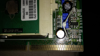
With two Super Slokets III I was able to use two celerons. No luck with Pentium

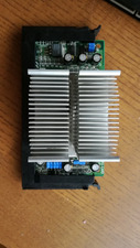
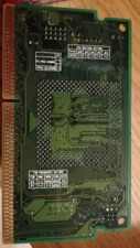
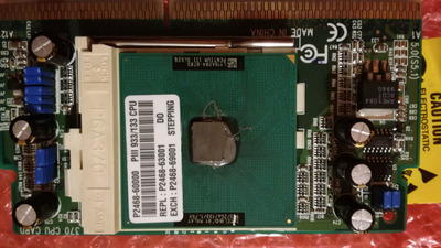
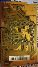
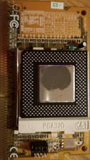
Then I found two "370 CPU CARD", very cheap.
Both with box and instructions. Seems pretty good with vrm onboard (I think) and a lot of jumpers.
But again, they work with Celeron only.
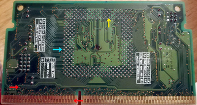
BTW I tried all combinations with J11 jumpers (supposed to be the one to play with in case of smp), no luck.
Here the manual : download/file.php?id=98175
The best thing that happened is to post with one cpu only visible.
Still I think they are very good, so can someone mod them for me?
I can ship both in EU... Am I desperate? Of course I am...

Let me know.

Attachments

  • IMG_20201220_153445.jpg
    Filename
    IMG_20201220_153445.jpg
    File size
    304.11 KiB
    Views
    1008 views
    File license
    Fair use/fair dealing exception
Last edited by Mamba on 2020-12-20, 17:06. Edited 3 times in total.

Reply 2 of 19, by Mamba

User metadata
Rank Oldbie
Rank
Oldbie

Yes it is,
and the author @PC Hoarder Patrol is in contact with me.
It seems his adapter worked in SMP with a legit ASUS S370-DL.
Maybe if you have an Asus, it is possible to use one. In any case I would like to make the mod on both given the very good capabilities they carry.
Please if someone would like to do it for me, we can arrange something for sure...

Reply 3 of 19, by PARKE

User metadata
Rank Oldbie
Rank
Oldbie

That sort of modding is outside my league. Because the subject interests me I looked into it but the actual deed is over my head.

Btw, I am not sure what you mean with [N33] mod ? As far as I can see that pin is "reserved for future use" on all PPGA and FCPGA cpu's.
(edit) never mind - found it

Reply 4 of 19, by Mamba

User metadata
Rank Oldbie
Rank
Oldbie

It is a mod frequently associated to MSI slotket, but it should not be limited to it.
In fact I found a page where a guy modified my "no brand" Super slotket III" and apparently they work...

http://www2b.biglobe.ne.jp/~houmei/rd/slocket3.html

Of course, if some mod should be done, I prefer to make the QDI adapters modded, since they are way better.

Maybe if someone would give me some insight on hw to to it, I could find someone here to do some soldering for me (even if I prefer your direct intervention guys).

Last edited by Mamba on 2022-05-08, 04:31. Edited 1 time in total.

Reply 5 of 19, by PARKE

User metadata
Rank Oldbie
Rank
Oldbie

The N33 reference also occurs in this german article:
http://www.hit-karlsruhe.de/aol2mime/slotket.htm

One link in that article leads to this site:
http://patswayne.com/megamod/
that describes a dual Tualatin mod with two different slotkets

Reply 6 of 19, by Mamba

User metadata
Rank Oldbie
Rank
Oldbie
PARKE wrote on 2020-12-22, 01:17:
The N33 reference also occurs in this german article: http://www.hit-karlsruhe.de/aol2mime/slotket.htm […]
Show full quote

The N33 reference also occurs in this german article:
http://www.hit-karlsruhe.de/aol2mime/slotket.htm

One link in that article leads to this site:
http://patswayne.com/megamod/
that describes a dual Tualatin mod with two different slotkets

Thanks, the second one talks about modification on the "Super Slocket III" adapter, I have two of them.

I wonder what kind of mods would be necessary for the QDIs, as I see them a lot more robust and capable.
Any expert out there?

Reply 7 of 19, by PARKE

User metadata
Rank Oldbie
Rank
Oldbie
Mamba wrote on 2020-12-22, 13:52:

Thanks, the second one talks about modification on the "Super Slocket III" adapter, I have two of them.

I wonder what kind of mods would be necessary for the QDIs, as I see them a lot more robust and capable.
Any expert out there?

But take note of the fact that these mods were done with the intention of using Lin-Lin adapters so it is possible that the method is different from the one(s) necessary for Tualatin cpu's (without adapters).
The more I read about it the more questions arise (for me), or so it seems.

In that first link it is reported that the Abit SlotKET !!! v1.2 supports SMP but also that it is limited to fsb 100.
As far as I have seen the only slotket that 'guaranteed' supports SMP is the Powerleap PL-P3/SMP but I suppose finding a set of those is a pipe dream. The ASUS S370-DL is suppposed to support SMP according to some reports on the web but according to the ASUS paperwork it is only quaranteed with PPGA Celerons (see attached) and possibly it works only with Coppermines on ASUS motherboards.
As a general obeservation - it seems to me that theoretically any slotket can be modded to do 'everything' but the trick is finding out what should be modded in any specific slotket/motherboard combination.

Attachments

  • Filename
    s370dl.pdf
    File size
    143.03 KiB
    Downloads
    34 downloads
    File license
    Fair use/fair dealing exception

Reply 8 of 19, by Mamba

User metadata
Rank Oldbie
Rank
Oldbie
PARKE wrote on 2020-12-22, 14:13:
But take note of the fact that these mods were done with the intention of using Lin-Lin adapters so it is possible that the meth […]
Show full quote
Mamba wrote on 2020-12-22, 13:52:

Thanks, the second one talks about modification on the "Super Slocket III" adapter, I have two of them.

I wonder what kind of mods would be necessary for the QDIs, as I see them a lot more robust and capable.
Any expert out there?

But take note of the fact that these mods were done with the intention of using Lin-Lin adapters so it is possible that the method is different from the one(s) necessary for Tualatin cpu's (without adapters).
The more I read about it the more questions arise (for me), or so it seems.

In that first link it is reported that the Abit SlotKET !!! v1.2 supports SMP but also that it is limited to fsb 100.
As far as I have seen the only slotket that 'guaranteed' supports SMP is the Powerleap PL-P3/SMP but I suppose finding a set of those is a pipe dream. The ASUS S370-DL is suppposed to support SMP according to some reports on the web but according to the ASUS paperwork it is only quaranteed with PPGA Celerons (see attached) and possibly it works only with Coppermines on ASUS motherboards.
As a general obeservation - it seems to me that theoretically any slotket can be modded to do 'everything' but the trick is finding out what should be modded in any specific slotket/motherboard combination.

You are correct.
I would be happy only to reach the dual cumine mod.
The dual Tualatin is another level.
The point is to find the proper scheme to make the mod (or to bring the scheme to someone with soldering tool to do it for you).
Of course people with the proper technical expertise and knowing coppermine/Tualatin spreadsheets can mod anything and I am sure that a ot of people can do.
The point it to have a very well built Slocket to work with and I am sure the QDIs are very good.

I hope someone will show up.

Reply 9 of 19, by PARKE

User metadata
Rank Oldbie
Rank
Oldbie

Maybe it can help if you post a high-res photo of the rear side of the QDI. If there are any stickers attached please remove.
The dual Coppermine mod looks relatively straightforward from the available documentation (depending on the slotket). Slot1 B75 to FCPGA N33 instead of to AN15 on dual PPGA supporting slotkets.
Some need an extra resistor, some don't.

Reply 10 of 19, by Mamba

User metadata
Rank Oldbie
Rank
Oldbie
PARKE wrote on 2020-12-22, 16:54:

Maybe it can help if you post a high-res photo of the rear side of the QDI. If there are any stickers attached please remove.
The dual Coppermine mod looks relatively straightforward from the available documentation (depending on the slotket). Slot1 B75 to FCPGA N33 instead of to AN15 on dual PPGA supporting slotkets.
Some need an extra resistor, some don't.

You are right again.
Here attached front and rear of the QDI.
The white spots are adhesive dirt.

Attachments

Reply 11 of 19, by Mamba

User metadata
Rank Oldbie
Rank
Oldbie

And here front and rear of the Super Slocket III

Both are dual mendocino and single cumine capable at 133mhz.

Attachments

  • IMG_20201222_223826.jpg
    Filename
    IMG_20201222_223826.jpg
    File size
    512.18 KiB
    Views
    811 views
    File license
    Fair use/fair dealing exception
  • IMG_20201222_223801.jpg
    Filename
    IMG_20201222_223801.jpg
    File size
    366.98 KiB
    Views
    811 views
    File license
    Fair use/fair dealing exception

Reply 12 of 19, by PARKE

User metadata
Rank Oldbie
Rank
Oldbie
Mamba wrote on 2020-12-22, 21:30:

Here attached front and rear of the QDI.

That does not bring much. The red arrows indicate the B75 track and it ends with a hole (through to the front ?)
Considering that the QDI claims to support dual PPGA the one scenario that makes the most sense is that pin AN15 (blue arrow) is somehow connected with B75.
Your option to allow dual Coppermine support would then be to isolate pin AN15 (blue arrow) on the socket side and solder a wire from AN15 to N33 (yellow arrow). Agree ?

IMG_20201222_222654a.jpg
Filename
IMG_20201222_222654a.jpg
File size
724.08 KiB
Views
775 views
File license
Fair use/fair dealing exception

Reply 13 of 19, by Mamba

User metadata
Rank Oldbie
Rank
Oldbie
PARKE wrote on 2020-12-23, 09:57:
That does not bring much. The red arrows indicate the B75 track and it ends with a hole (through to the front ?) Considering tha […]
Show full quote
Mamba wrote on 2020-12-22, 21:30:

Here attached front and rear of the QDI.

That does not bring much. The red arrows indicate the B75 track and it ends with a hole (through to the front ?)
Considering that the QDI claims to support dual PPGA the one scenario that makes the most sense is that pin AN15 (blue arrow) is somehow connected with B75.
Your option to allow dual Coppermine support would then be to isolate pin AN15 (blue arrow) on the socket side and solder a wire from AN15 to N33 (yellow arrow). Agree ?IMG_20201222_222654a.jpg

Hello again,
I was able to identify the hole on the other side. It is the one on with the pin point on it.
It leads to... Another hole!
On the second photo there is another pinpoint this time leads somewhere...
If I am correct it seems to lead to pin-2 of J11 (the 4pin jumper for cumine/dual celeron operations). There is another hole in the middle, but on the other side I do not see traces, it is near R33.

Does it help?

Attachments

Last edited by Mamba on 2020-12-23, 17:12. Edited 1 time in total.

Reply 14 of 19, by PARKE

User metadata
Rank Oldbie
Rank
Oldbie
Mamba wrote on 2020-12-23, 14:15:
I was able to identify the hole on the other side. It is the one on with the pin point on it. It leads to... Another hole! On th […]
Show full quote

I was able to identify the hole on the other side. It is the one on with the pin point on it.
It leads to... Another hole!
On the second photo there is another pinpoint this time leads sonewhere...
If I am correct it seems to lead to pin-2 of J11 (the 4pin jumper for cumine/dual celeron operations). There is another hole in the middle, but on the other side I do npt see traces, it is near R33.

It suggests that B75 may indeed (not surprisingly) be connected to AN15 via the dual celeron jumper block and that the fix that I suggested is ok.
In an on-line article about modding an ABIT BP6 dual Celeron motherboard I found this piece of text that explains the background of the proposed mod a bit:
000000000000000
AN15
This pin is the BR1# signal on the Celeron. Intel denies the Celeron core is SMP capable so this pin is marked as Reserved in all datasheets. The BR1# signal is used to select the agent in a symmetric multiprocessor system. The corresponding pin on the Coppermine should be X2 according to Intel and is only validated for steppings above or equal to cB0. The position for this signal for stepping below cB0 is N33 according to various reports found on the Internet. At first I though that the AN15 signal must be connected to one of these two pins according to the CPU stepping.
However, this is not true.
The BR1# pin is actually N33.
What needs to be done here is - remove the AN15 socket pin on both sockets in order to break the connection between AN15 processor pin and the motherboard.
Connect AN15 motherboard trace to N33 motherboard trace on both sockets to wire the Coppermine BR1# signal.
000000000000000

You live in a big city and it should be possible to find a shop locally that does this kind of slightly old fashioned electronic repairs on printed circuit boards. That seems a better option than sending the QDI cards to 'someplace' via mail.

Reply 15 of 19, by Mamba

User metadata
Rank Oldbie
Rank
Oldbie

At the moment you are my almighty god so thank you.
As I am a stupid, could you please specify in details (maybe with your arrows scheme) what should I do or tell to do?

And, because I am stupid I do stupid questions, what about a wire fron N33 to pin2 on j11 without isolating an15?
Maybe in this way it could work both for mendocino and coppermine smp, following j11 configuration?

Thank you so much

Reply 16 of 19, by PARKE

User metadata
Rank Oldbie
Rank
Oldbie
Mamba wrote on 2020-12-23, 16:48:
...could you please specify in details (maybe with your arrows scheme) what should I do or tell to do? 8><CUT And, because I am […]
Show full quote

...could you please specify in details (maybe with your arrows scheme) what should I do or tell to do?
8><CUT
And, because I am stupid I do stupid questions, what about a wire fron N33 to pin2 on j11 without isolating an15?
Maybe in this way it could work both for mendocino and coppermine smp, following j11 configuration?
8><CUT

Maybe your best option for this endeavour is not to get yourself involved with mods/hacks at all but to start hunting for a couple of ASUS S370-DL slotkets. Although that kind of slotket is rather expensive it may in the end prove to be the cheapest solution. Besides that, owning a set of ASUS S370-DL slotkets working on an ASUS motherboard is a bonus.

Re your second question... I have no idea what the result of the N33 mod in combination with leaving the AN15 intact will be. But I strongly advise you not to try it out without some back-up info claiming that it is even possible to result in a booting computer without blowing things up..

Reply 17 of 19, by Mamba

User metadata
Rank Oldbie
Rank
Oldbie

Getting two Asus could cost me a leg.
Find someone here that can do the job following precise instructions is extremely less expensive.
As said, my idea was stupid.
I will follow you inputs.
To isolate AN15 means to cut the trace?

And speaking of the super slocket III, the guy in the link connected N33 to pin3 of jp3.
Does it make sense to you?

Reply 18 of 19, by PARKE

User metadata
Rank Oldbie
Rank
Oldbie
Mamba wrote on 2020-12-23, 19:54:

To isolate AN15 means to cut the trace?

And speaking of the super slocket III, the guy in the link connected N33 to pin3 of jp3.
Does it make sense to you?

There are different ways to isolate socket pin AN15 from the CPU. Cutting the trace is one option. Cutting the pin from the cpu is another. Removing the pin from the socket altogetherwill work too, but the method that does -not- do any damage is slipping a small piece of sticky tape in the pin hole of the socket. The latter method is described here:
https://www.oocities.org/_lunchbox/generic_slotket_mod.html
(scroll down to step 1)

JP3 on the Super Slocket III enables the connection between B75 and AN15 so that makes sense. It does not matter much from which point of the B75 track you make the connection with N33.