tony359 wrote on 2023-03-08, 21:38:
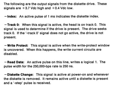
What is exactly the "diskette index" pulse? What is its purpose?
It's for the FDC to be able to tell where sector 1 should begin. One could make a system without it, based on simple timers (if the drive spindle is stable in rpms) but it makes things easier. You know the drive has a disk in it and it's spinning with the pulse, you can tell how fast it's spinning, and early FDCs required this signal to make sure the format you are trying to apply to the disk does not have more sectors than the track can hold.
In general, no index signal (or erratic) and the drive will not work. Might even refuse to work already at the chip level on the drive side, some of the smarter chips need to see the index pulsing to tell a valid floppy is inserted, also to stop the initial motor spin on insertion (which is it help center the disk properly). A drive that outputs READY signal must see the pulse, and it must fall within pretty narrow timing window, for that signal to go active.
On 5.25" and 8" floppies the index come from the hole near the center, on 3.5" the spindle motor has a sensor for that. Older system could get dirty and stop working, the magnetic sensor pretty much never fails - it's a coil that picks up magnetic field from part of the wheel which is unmasked (no metal cover over it). Sometimes the sensor is SMD, on the PCB under the magnet in the wheel. Corroded leads, traces or cracked solder (or the flex cable between spindle and main PCBs) can mess up that signal.
One more thing you should check - floppy drives have O/C ouputs and need pull-up resistors for each signal. This is usually a resistor pack, often called a terminator although it's not what it's for (but it serves that purpose too). Older drives have 150 ohm pack and only the last drive on the cable should have one installed. That pack is removable, there is a socket for it. Newer drives are "auto-terminated", which is fancy name for a permanently soldered pack of 680 ohm to a few kohm resistors. This limits the cable length to some 50 cm but that's still more than what typical modern PC will have, plus you can have the pack on each drive and not have to mess with it.
Point here is - check those pull-ups, any problems with those (too high resistance, broken connection, etc) will give you semi-random readings. Also do not mix new and old tech, there can be only one low-value pack on the cable. If you have 2 drives and one is auto-terminated and the other has a removable pack, the pack needs to go. Having the pack installed not at the end of the cable might give you some more R/W errors but nothing as bas as you have now.