VOGONS


Reply 40 of 47, by Deunan

User metadata
Rank Oldbie
Rank
Oldbie
tony359 wrote on 2023-03-08, 23:35:

However I am a bit confused: shouldn't the controller on the motherboard complain that the index pulse is not present all the time? How come it works and only the IBM diagnostic utility complains about that?

Index pulse is mostly useful for writing, or rather low-level formatting. Everything else just accepts the stream as it's laid out (writing too, it looks for sector sync headers). That's why I said in theory the index could be missing entirely and you'd still have a working drive, but it's useful thing to have. You need it for proper track-to-track sector skew, though anything faster than 8MHz 286 or so would not care much for that.

tony359 wrote on 2023-03-08, 23:35:

I am not sure I understand the "some of the smarter chips need to see the index pulsing to tell a valid floppy is inserted, also to stop the initial motor spin on insertion" - are you referring to the 5.25" disks where the pulse was coming from the hole on the disk?

This also applies to 3.5" drives that ouput READY signal. It's not used on PCs but the chips are not made just for PCs, these are usually pretty universal an configured on the PCB - either via jumper or permanently via solder bridges or 0 ohm resistors. 5.25" drives will use it to stop the motor during insertion/clamping, 3.5" migt use a timer or count the pulses for that purpose.

tony359 wrote on 2023-03-08, 23:35:

On this drive the pulse comes from the flywheel (or maybe I've been calling it wrong and it's the rotor, or stator?) so it's always there.

It's a direct drive - both rotor and flywheel to provide some extra mass to stabilize the rotation speed. But I prefer to call it rotor since you can do without a flywheel but not a rotor.

tony359 wrote on 2023-03-08, 23:35:

I think on this drive the item which tells the logic there is a disk inserted is a microswitch which gets pressed when the disk is inside. Indeed I've noticed this triggers the "disk changed" pin.

That's the usual way to do it on 3.5" drives, and that switch can corrode inside (on some particular machines it's pretty much given and these must be cleaned, which is tricky, but PC drives tend not to have this issue).

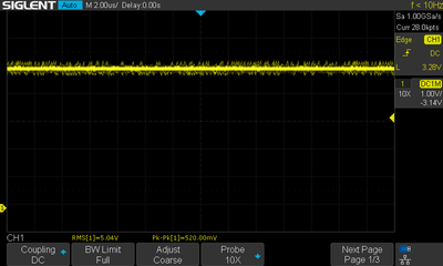
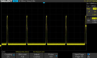
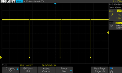
BTW, when I mentioned the pull-ups I wanted to bring your attention to the fact that floppy drives use a shared bus. It's easy to forget that, especially with just one drive on the cable. All the output signals from the drive are gated by the select signal, so if that is wonky somehow the drive might seem to have erratic output - but in fact is working properly and it's the input that's the problem. If you see the /INDEX line high when it should be toggling you can suspect /SEL (and monitoring /RDATA at the same time will help you out, it would also go high). Too long or semi-permanent low on /INDEX should not happen on 3.5 drives if the pull-ups are properly connected, that would indicate a chip failure or some serious problems with power supply or filtering on the drive itself. But it's normal on 5.25" drives with no floppy inserted for example.

Reply 41 of 47, by tony359

User metadata
Rank Member
Rank
Member

Thank you a lot!

I've done further tests and I can confirm my Panasonic drive - via adaptor - shows the index pulses and everything is happy with it including IBM diagnostic. The PS/2 drive does not show pulses - it's a high signal with no pulses. If I keep scoping, sometimes those pulses appear.

I followed the trace from the INDEX pin, I reached a buffer but there were no pulses on its input either. The next trace took me to one of those chips I can't find any info about. Unfortunately it's not outputting pulses either. And I guess my quest ends here as 1. I cannot find any info about it 2. I cannot find a replacement. Again, I see those pulses around the board, they are definitely coming from the magnet on the rotor.

Unless any of you can help, it's a mitsubishi chip labelled M52800FP. The other IC on the board is a Mitshubishi M51018AP.

I appreciate it could be something else not sending the signal INTO one of those chips but with no datasheet it's impossible to know I guess.

Thanks all for your help!

My Youtube channel: https://www.youtube.com/@tony359

Reply 42 of 47, by Deunan

User metadata
Rank Oldbie
Rank
Oldbie
tony359 wrote on 2023-03-10, 16:51:

Unless any of you can help, it's a mitsubishi chip labelled M52800FP. The other IC on the board is a Mitshubishi M51018AP.

Can you make a photo or two of the PCB and chips? And try to trace the drive select signal as well, see if it's going from the cable/connector to the chips.

Reply 43 of 47, by tony359

User metadata
Rank Member
Rank
Member

Sorry Deunan, I forgot to mention that I did scope the Drive Select line and I did not observe any issues there. The line is triggered whenever the drive is being used, it's not intermittent or anything.
I've checked and I managed to track the DS line up to the same Mitshubishi chip from which the INDEX pulse should be output.

PCB pictures attached. The suspected chip is the square one on bottom left of the picture.

Thank you for not giving up on this, I appreciate it. I would love to fix this thing 😀

Attachments

  • IMG_3893.JPG
    Filename
    IMG_3893.JPG
    File size
    1.92 MiB
    Views
    318 views
    File license
    Public domain
  • IMG_3892.JPG
    Filename
    IMG_3892.JPG
    File size
    1.77 MiB
    Views
    318 views
    File license
    Public domain

My Youtube channel: https://www.youtube.com/@tony359

Reply 44 of 47, by Deunan

User metadata
Rank Oldbie
Rank
Oldbie
tony359 wrote on 2023-03-11, 09:56:

PCB pictures attached. The suspected chip is the square one on bottom left of the picture.

I spy two little solder blobs that aren't shorting anything as far as I can tell but you might want to get rid of them anyway. One is top side on the pins of IC7, on the side of the edge connector. Another is bottom side on what looks to be 4-pin connector (the lowest one).

As for the M52800FP, I have not found it either but it should be a pretty dumb timing sequencer. It has some logic but not much, mostly various timers that control things - like step pulse length and current reduction, spindle motor timout, that sort of stuff. For all that it needs a clock and that's the blue box X-something nearby. See if the clock is present and stable (10:1 scoope probe might be required to not dampen the oscillations). If not then inspect nearby C16, C17 and R12. Also check power, it seems to come to nearby CP2 and CP3 - there might be some noise and ripple, but I'd say nothing worse than 0.5V

Also there is a test point bank nearby, marked TP with numbers 4-7. One of those should have the index pulse, usually it's TP7 but that's not exactly a standard, check all of them.

Reply 45 of 47, by tony359

User metadata
Rank Member
Rank
Member

Thanks again for your time.

Attached some pictures.

VCC is fine, scope says 520mV p/p of "noise" more than ripple. This is with a short ground lead but attached on the chassis of the drive, not the ground pin
Clock is fine, 399Khz, the chip says 400 on it.

Pin 7 is ground
Pin 6 is indeed the index pulse (below)
Pin 5 is track zero (I captured a moment when I was running a head exercise SW so the head was travelling back and forth)
Pin 4 is data

Pin 6 does not come from the Mitsubishi chip.

I suspected that that chip had some basic logic to look after. Unless you or anybody else has other ideas, I guess my only option is to find a broken drive and replace that chip 😀 I have ordered the remaining logic chips, I can try to replace them but they test ok so I doubt it will improve things. I could try to properly test all the other transistors just in case - I have tested all the passive components.

To be fair, the drive stops responding every now and then - I see the controller sending steps but the head does not move. I think the missing index pulse is just a symptom of a failing IC there.

Too bad, I was almost there.

Attachments

  • VCC.png
    Filename
    VCC.png
    File size
    23.16 KiB
    Views
    291 views
    File license
    Public domain
  • Track zero.png
    Filename
    Track zero.png
    File size
    20.86 KiB
    Views
    291 views
    File license
    Public domain
  • Index.png
    Filename
    Index.png
    File size
    12.19 KiB
    Views
    291 views
    File license
    Public domain
  • Data.png
    Filename
    Data.png
    File size
    33.99 KiB
    Views
    291 views
    File license
    Public domain
  • Clock.png
    Filename
    Clock.png
    File size
    23.39 KiB
    Views
    291 views
    File license
    Public domain

My Youtube channel: https://www.youtube.com/@tony359

Reply 46 of 47, by Deunan

User metadata
Rank Oldbie
Rank
Oldbie

Well, I'm out of ideas. If you have more problems than just the index pulses missing then I would suspect the Mitsubishi chip slowly failing as well. Might be difficult to find it, this looks to be a rather early 3.5" drive, the ones I'm most familiar with are more modern (1 or 2 SMD chips). I think the oldest 3.5" I have is already HD capable and has 3 SMD chips and not 2 only because of external coil driver for stepper motor.

Reply 47 of 47, by tony359

User metadata
Rank Member
Rank
Member

Well the main issue is that every xx minutes the drive stops working. I think the index pulse is only preventing the formatting and the IBM diagnostic which seems to look for that signal.

Too bad, I fixed the motor, the logic but there is something else... At least I can use a modern drive with this PC. But I'd love to have an original drive on this thing. I'll keep an eye on Ebay to see if I can find one - or another drive.

For now, really thank you for your help on this project - it's been fun!

My Youtube channel: https://www.youtube.com/@tony359