First post, by Brute389
Hello everybody,
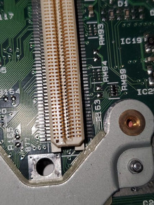
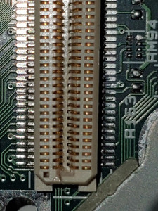
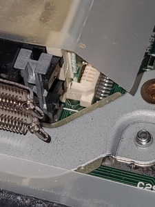
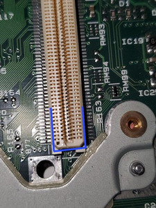
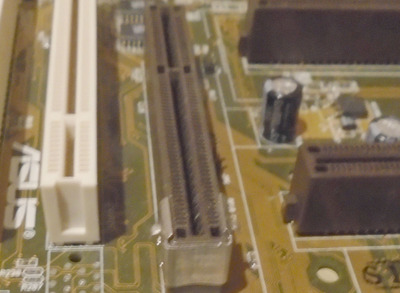
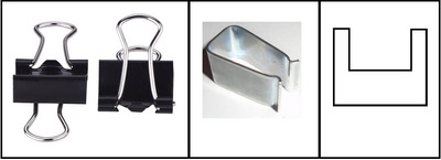
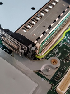
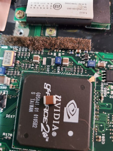
I am asking for help in trying to fix a cracked plastic pcb connector slot that my PCMCIA board connects into on my laptop's motherboard. I discovered the crack initally after realizing none of my PC cards were being detected despite the PCMCIA hardware working normally. So I tried fixing the crack by using JB PlasticWeld and letting it cure for a day. The PCMCIA board kinda works, but I keep getting a code 10 error when I try to install drivers for any PC cards. The code 10 error I believe is due to the slot having been widened and cracked so that it is not producing a good enough connection to deliver enough power. So, it did not work, and I took apart the machine again to find the same crack reappearing as in the photos attached. So I'm lost on how to proceed as I used a really strong epoxy that ended up failing, and am looking for advice on what to do next. Thanks.