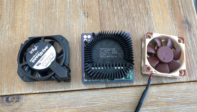
Yesterday I received my 200 MMX Overdrive 😀 Another piece of gear I was looking up to in the 90s but never could afford 😉 NOS, which felt really strange - anyway.
This is a third world problem, but I think the fan is really loud. I was wondering, if anyone has ever done a fan replacement. As known, the CPU clocks down when the stock fan is removed. The three pins output GND, 0V and 5V constantly, as far as I could measure.
Was there ever a successfully completed project of that sort? Also, does anyone know, what load will trigger to disable the overheat protection, or if it requires anything more sophisticated other than connecting another 5V fan to it?
Oh sorry. My bad, it is non-MMX overdrives that don't slow down. The MMX is indeed throttling (but not slowing the clock speed like the 83 MHz) - Tested them here
In that case you will probably need to hack the fan to the 3 pins on the CPU 🙁
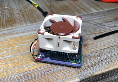
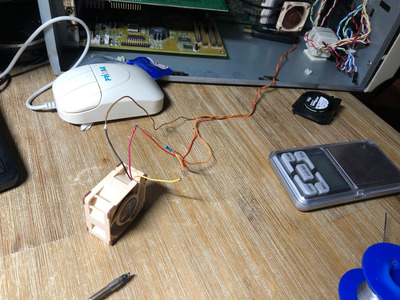
So, I soldered a 5V Noctua fan 0.5W 0.1A black/yellow/green to the CPU.
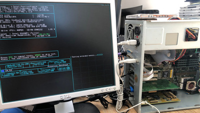
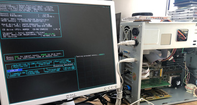
It scores 116 points in the processor benchmark, compared to 134 points with the stock fan, and 24 without a fan.
The stock fan shows 0.14A on the sticker. I will look for another fan with the same power draw, unless anyone has another idea. Noctua is extremely silent at 14.9dB.
I wonder if the Noctua is drawing more power than the stock Intel fan, and the CPU is intelligent enough to see this increased power draw as something it should throttle against?
I think the CPU can supply 200mA to the fan (from a datasheet I found). The Noctua is rated at 100mA and the stock at 140mA. So the CPU could be throttling because the Noctua isn't drawing as much current, but I wouldn't guess that. Perhaps the problem is with the tachometer signal from the fan to the CPU (yellow wire I think).
Can you leave the wires in place and still fit the stock fan, and then measure the voltages on the pins (ideally an oscilloscope if you have one) when the fan is running? The Noctua probably puts out a series of pulses (twice per revolution), which might keep flicking the CPU down to 1x. Something that's slightly risky because we don't know exactly what the pins are, but might work, would be to connect a 1k resistor between the +5 pin and the tachometer and see if that makes a difference. I'm wondering if the stock fan outputs a voltage proportional to RPM, rather than the normal pulses, then the CPU goes to full speed once the voltage crosses a threshold. The resistor should limit any currents if this doesn't work.
Thanks guys. Not only am I missing an oscilloscope, but also experience with electronics... I am OK soldering things together, and measuring stuff with a multimeter, but not much more than that...
I have measured the fan pins on the CPU before I soldered them. Left to right it is GND, Yellow, and +4.9V. Yellow was almost zero V.
@snufkin 1K resistor - as in 1.000 Ohm? Can I just use anyone I find online or does it have to be more specific for this case?
@maxtherabbit So I guess either I manage to trick the CPU into thinking the tach signal is present, via the 1k resistor mod, or I just have to have luck and find a fan that matches the tach signal good enough.
Or I call it a day and leave it as it is, and live with the noise.... nah.. ^^
Thanks guys. Not only am I missing an oscilloscope, but also experience with electronics... I am OK soldering things together, and measuring stuff with a multimeter, but not much more than that...
You can generally get by with a multimeter. Half of all this trying to make old stuff work seems to be making sure stuff that should be connected is, and stuff that shouldn't be isn't. A scope means you can actually see the detail of the signal, a meter only really gets you an average. So you won't see the individual ticks on the tach signal, but should still be able to see if there is any signal (if it stops reading zero).
I have measured the fan pins on the CPU before I soldered them. Left to right it is GND, Yellow, and +4.9V. Yellow was almost zero V.
Was that with the stock fan in place? It didn't look like the pads would be accessible to probe when the fan was there. If the fan wasn't connected and spinning then what you'd measure might just be a floating (not actively driven by anything) signal in to the CPU. If it was with the stock fan in place, then measure the same thing with the Noctua and see if there's any difference. Effectively compare the tach output from the fan to the CPU for the difference fans.
@snufkin 1K resistor - as in 1.000 Ohm? Can I just use anyone I find online or does it have to be more specific for this case?
Yes, as in one thousand. I had a moment of confusion when I read that as one-point-zero ohms, which would be bad. One of those different usages of '.'
For a quick test, anything'll do if you can borrow one from another bit of hardware. If it works then you can worry about finding a permanent replacement. Doesn't need to be exactly 1k, but don't go much lower or (if I'm wrong) the current will get bigger, which might damage things. 5V across a 1k resistor is 5mA, so shouldn't be enough to break anything.
If I'm wrong then the most likely thing will be that the CPU will behave as though the fan isn't spinning as it won't see any changes on the tach line and should go back to normal when you remove the resistor. Oh, and if you do try this, try it first without connecting the yellow wire in case the signal from the Noctua is what's causing the problem.
But I'd only have a go doing this after confirming what the Tach / Yellow pin voltage is when the fans are running.
Or I call it a day and leave it as it is, and live with the noise.... nah.. ^^
My suggestions in order of preference:
1) cope
2) try the pullup resistor. The same issue occurs when noctua modding a sega dreamcast btw. You need a pullup to make the tach work to get the console to boot. You think the POD is loud the dreamcast is 10x worse
Idea: Somebody could use an arduino to fake the tachometer signal.
Additionally you could put a switch in the tachometer wire to throttle the CPU; turbo switch style.
Alright alright. I am going to test and post results.
Just to double-check: It does not make a difference if I solder the resistor to the CPU pins (+5v and yellow), or somewhere across the +5v and yellow cable - right? Also polarity does not matter with resistors?
@snufkin - Sorry for the 1.000 - German notation. 1,000 / 1kOhm. The pins of the integrated fan are accessible for measurement if you partly peel off the sticker at the top.
I didn't know that about the dreamcast, thanks maxtherabbit. And I like the idea of a turbo switch, Doornkaat.
I think if you can have just the resistor on the tachometer input on the CPU to start with and see what (if any) effect that has. If you connect it across the red and yellow wires from the fan then there'll still be the output from the fan, which might confuse things.
Things that I think would be useful to confirm with your multimeter and a quick CPU speed test, all relative to the Gnd pad:
Voltage on the CPU tach input and CPU speed with:
1) no fan fitted (CPU should be in 1x mode, so passive cooling from the heatsink should be ok)
2) with the stock fan fitted (speed should be full speed)
3) with the noctua fitted (based on earlier testing, speed should be a little slower than full speed)
4) with a resistor from the tach input to +5 and the Noctua fitted, but without connecting the yellow wire
5) as 4, but connecting the yellow wire
Oh, and take two readings for each of those, one with the probes swapped round. So first black probe on Ground and red probe on tach input, then with red probe on Ground and black probe on tach input. In theory they should be the exact mirror of each other (+ve the first time, -ve the second time), but on my cheap meter I get different numbers if the signal is switching.
I remembered about the different notations a second after I saw it, it was just a moment of "Good grief, no, not one ohm!", before realising that you had it right.
Ranking the sketchiest things I have done so far, this is a solid 3rd place. Note that some of the measured values involving the tach line jump around a bit, so I estimated the average:
1) no fan fitted (CPU should be in 1x mode, so passive cooling from the heatsink should be ok)
GND/Tach -3.357V
GND/Red 1.569V
Tach/Red 4.94V
Benchmark 24.53 points
2) with the stock fan fitted (speed should be full speed)
GND/Tach -48mV
GND/Red 4.82V
Tach/Red 4.87V
Benchmark 134.29 points
3) with the noctua fitted (based on earlier testing, speed should be a little slower than full speed)
GND/Tach -1.2V
GND/Red 3.75V
Tach/Red 4.92V
Benchmark 122.00 points
4) with a resistor from the tach input to +5 and the Noctua fitted, but without connecting the yellow wire
GND/Tach -4.11V
GND/Red 0.83V
Tach/Red 3.86V
Benchmark 24.53 points
Noctua not spinning
5) as 4, but connecting the yellow wire
GND/Tach -1.2V
GND/Red 3.6V
Tach/Red 4.92V
Benchmark 121.35 points
Wow, those numbers are unexpected. The voltage from GND to Red/+5 should always be around 5V, maybe a bit less as more current is drawn. And there shouldn't be anything -ve. And the Noctua not spinning in test 4. Can I check what the colour banding on the resistor is? And if you don't mind my asking, how did you identify which pad on the CPU was which? The numbers make more sense to me if GND and Tach are swapped round. That would make it:
If it's like that, then you can see that if you add the top two rows (ignore the minus sign) they add up to around 5V. So the voltage from GND-Tach + Tach-5 is the same as GND - 5
From your photo (thanks) that makes GND the orange wire and Tach the brown wire. You should be able to confirm GND by measuring (with computer off) resistance between a GND on a molex power connector and the orange and brown wires (so black-orange and then black-brown).
This possible swap also explains why the Noctua didn't spin for test 4, it might have been connected from +5 to the Tach input, so there's no circuit, so no current flows.
Also on the upside, if I'm right about that, some useful measurement there. We can see it runs slowest when the Tach input is up around 3-4V and fastest when it's at 0V. We can also see that with nothing connected to Tach it floats up to 3.4V. So it looks as thought the CPU is running at full speed when Tach is pulled to ground.
So, I think the thing to try is first try connecting the noctua Red+Black wires to 5 (red) and GND (orange?) and check it spins. The CPU should be at 1x at that point. If it doesn't spin then we'll need to check a few things on the fan and those CPU pads. If it does spin then run the benchmark and check the speed is slow. Then turn off and attach the 1k resistor from GND to the tach wire (brown?) going to the CPU and mount the Noctua. That should have the CPU running full speed. Leave the yellow noctua wire disconnected.
If that does make it run at full speed, great. Probably worth pointing out that this does mean that if the fan fails then the CPU won't know and will carry on at full speed and get a bit toasty.
Ranking the sketchiest things I have done so far, this is a solid 3rd place. Note that some of the measured values involving the tach line jump around a bit, so I estimated the average:
Only 3rd? I'll have to try harder.
The jumping around is probably the ticks that the fan puts out on the tach line. Multimeters don't handle measuring signals very well.
Good find, yes that looks the same. Looks like confirmation that the Tach/Sense pin needs to be pulled low to get the CPU to run at full speed.
I like Matze79's suggestion of not bothering with the resistor and just drawing with a pencil to join the GND and Sense/Tach pads.
I've been trying to think if there's an easy way to set up a watchdog on the Tach output from the fan, and if it doesn't get triggered at least every (say) 0.1s then it disconnects the Tach input from the GND. That way the CPU will slow down if the fan stops. But I don't know enough about how exactly the Tach output from the fan works.