VOGONS


First post, by waterbeesje

User metadata
Rank Oldbie
Rank
Oldbie

Lately I've acquired an Intel Tiger Eye TE430VX motherboard. Traded it in for a 360k floppy drive.
I've put in a P200MMX and a 32MB SDRAM stick that are known good.

Now I know this board is Dell OEM branded, from a XPS M166S (or M200S or M233S) and carefully churches the ATX power connector.
The power connector turns out to be a regular ATX, not the Dell pinout (measured which contacts are connected internally) and no separate 3,3v plug. I connected the power connector and the thing powered on instantly. Yay!

All send well at first, but BIOS settings are not stored. The jumper for BIOS reset is set for normal operation and I replaced the CR2032 coin.

Now I powered it down with a random switch I've connected, and connected a (known good) CF adapter and card. Pressed the switch again and no power on.

It eventually powered back on only when I've had the power cord and battery disconnected for a couple of minutes. Again instantly when power was connected.
And again: no BIOS info can be stored, and after turning it off it won't power on with the switch.

Does anyone know what can cause this weird behaviour?

Edit: jumpwiring the PSU will start the system, still no BIOS options saved.

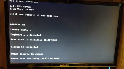
Now I've got the message "nvram cleared by jumper" (double checked the jumper position)

Boot from FDD is ok, but not from CF (but is detected and accessable)

Last edited by waterbeesje on 2021-05-14, 11:43. Edited 1 time in total.

Stuck at 10MHz...

Reply 1 of 14, by evasive

User metadata
Rank Oldbie
Rank
Oldbie

Can we have a picture of the capacitors on the board? I'm starting to think they are near blowing out. Either that or the power supply has an issue.
I hope the CR2032 was brand new out of the blister package and the expiry date is not passed.

Reply 2 of 14, by JidaiGeki

User metadata
Rank Oldbie
Rank
Oldbie

I had one of these boards from Gateway 2000 back in the day, I don’t think it supports MMX processors. When it was getting long in the tooth the upgrade path needed a special Unicore-made BIOS to support non-Intel CPUs which I bought but couldn’t get it to flash. If you have one try a regular Pentium 200, or maybe you might have luck with an MMX Overdrive.

Also, if it’s like the Gateway the RAM is extremely finicky, only 2-clock SDRAM or EDO. Had a hard time upgrading it.

Refer to https://forums.anandtech.com/threads/question … out-mmx.415409/

Reply 3 of 14, by waterbeesje

User metadata
Rank Oldbie
Rank
Oldbie

The board is branded Dell MxxxS, here xxx is the cpu speed. The M stands for the MMX support. If you had the PxxxS board, it only supports P54 and no P55. This board also "ran" with a P133 mounted (and configured as P100 to get things safe).

The coin is brand new indeed and well within expiry date, still measures 3,01v.

And the PSU is good, perfect voltages and provides more than double the required amps. I also checked with two other known good PSUs to be sure.

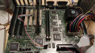
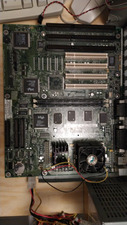
For caps: I'll take some good close up pics soon, but already attached an overall view. Things look to be ok if you ask me...

Attachments

Stuck at 10MHz...

Reply 5 of 14, by chrismeyer6

User metadata
Rank l33t
Rank
l33t

Did you try reversing the jumper just in case the silkscreen is wrong? Probably a long shot but is the board grounding out on the case of possibly a rogue screw under the motherboard?

Reply 6 of 14, by waterbeesje

User metadata
Rank Oldbie
Rank
Oldbie

Thanks for thinking along!

The traces might be the issue, I've thought about it too. Last Friday I tried to follow the current, but failed to... Probably a sip too much of the prosecco. 😜 I'll try again soon.

For grounding and stuff: I've improvised a testing bench from an old case, witch still had the ground plate and back side, including the PSU mounting. So that's still all connected as it should.

Reversing the jumper has no effect as well unfortunately, tried that too.

Stuck at 10MHz...

Reply 7 of 14, by weedeewee

User metadata
Rank l33t
Rank
l33t
waterbeesje wrote on 2021-05-15, 19:19:
Thanks for thinking along! […]
Show full quote

Thanks for thinking along!

The traces might be the issue, I've thought about it too. Last Friday I tried to follow the current, but failed to... Probably a sip too much of the prosecco. 😜 I'll try again soon.

For grounding and stuff: I've improvised a testing bench from an old case, witch still had the ground plate and back side, including the PSU mounting. So that's still all connected as it should.

Reversing the jumper has no effect as well unfortunately, tried that too.

Seems simple enough to measure the VBAT pin on the FDC37C932FR 😋

That reminds me that I still have to replace one of those on my dual p2 board 😐
I managed to destroy the keyboard inputs... at least got some memories from mekka symposium party, late 90's

Which reminds me... you sure the jumper isn't faulty?
Nothing more silly than a plastic jumper that lacks the conductor to be actually useful

Right to repair is fundamental. You own it, you're allowed to fix it.
How To Ask Questions The Smart Way
Do not ask Why !
https://www.vogonswiki.com/index.php/Serial_port

Reply 8 of 14, by waterbeesje

User metadata
Rank Oldbie
Rank
Oldbie

Vbat on FDC37C932FR... Never thought about that :x I'll check it! (Do you know which lead it is? I Will look up the datasheet ones of these days)

So this chip might be failing? Could something have triggered that? The keyboard seems to work ok.

The jumper is fine, it does have the metal pieces and I've tried with a few spare jumpers I've got laying around (and all fancy colours ofc) without success. Also no sign of corrosion, on both the pin and jumper (or battery holder)

Stuck at 10MHz...

Reply 9 of 14, by weedeewee

User metadata
Rank l33t
Rank
l33t
waterbeesje wrote on 2021-05-15, 21:03:

Vbat on FDC37C932FR... Never thought about that :x I'll check it! (Do you know which lead it is? I Will look up the datasheet ones of these days)

So this chip might be failing? Could something have triggered that? The keyboard seems to work ok.

The jumper is fine, it does have the metal pieces and I've tried with a few spare jumpers I've got laying around (and all fancy colours ofc) without success. Also no sign of corrosion, on both the pin and jumper (or battery holder)

I looked it up, it was a corner pin... 121 or so, though I'm kinda wondering if it goes through the jumper.
http://pdf.datasheetcatalog.com/datasheet_pdf … FDC37C935FR.pdf
page 4, top right corner.

Right to repair is fundamental. You own it, you're allowed to fix it.
How To Ask Questions The Smart Way
Do not ask Why !
https://www.vogonswiki.com/index.php/Serial_port

Reply 10 of 14, by waterbeesje

User metadata
Rank Oldbie
Rank
Oldbie

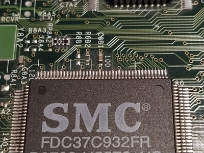
So I've checked the Vbat on the FDC37... Chip. It is connected to the + from the battery. Also when I measure the pin 121 (Vbat ) there is a clean 3.01V as it should.

IMG_20210517_215837.jpg
Filename
IMG_20210517_215837.jpg
File size
1.35 MiB
Views
486 views
File comment
SMC chip
File license
Fair use/fair dealing exception

Here is the obvious SMC chip. Lead 121 is not hard to find (and I did check the datasheet from your link).

IMG_20210517_215709.jpg
Filename
IMG_20210517_215709.jpg
File size
885.58 KiB
Views
486 views
File comment
battery holder
File license
Fair use/fair dealing exception

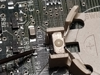
Here's the battery holder. It's current is held back by the resistor I'm pointing out. I've measured the loop from below this one and the multimeter went beep. The resistor measures 2,21k ohm. The loop above the resistor to the battery holder also beeps.

Still no BIOS saved 🙁

Stuck at 10MHz...

Reply 11 of 14, by weedeewee

User metadata
Rank l33t
Rank
l33t

I'm looking at the datasheet wondering about the oddness of your situation and you measure a new coin cell as 3v ... which is about .3v less than the new coin cells that I've measured here.

Anyway, Just to be ask. Date and time are also not kept when you turn the machine off. right ?

Right to repair is fundamental. You own it, you're allowed to fix it.
How To Ask Questions The Smart Way
Do not ask Why !
https://www.vogonswiki.com/index.php/Serial_port

Reply 12 of 14, by waterbeesje

User metadata
Rank Oldbie
Rank
Oldbie

It's been a while, had some family stuff to take care of.
Any way, I've hooked up the board again and indeed: date and time are reset as well. So the coin cell does provide some power to the FDC37C932FR but it's not doing anything useful.

As for the cr2032: this is designed to measure around 3,0v, but indeed: with open circuit it should be a few tenth higher (as you've measured). I'm going to look into for a better battery next time. This may just be a dud, since the batteries in this package all are still working fine (7/10 in use, mainly in motherboards)

Stuck at 10MHz...

Reply 13 of 14, by waterbeesje

User metadata
Rank Oldbie
Rank
Oldbie

Ok so the battery was a dud. I've placed a new one, re checked the jumpers and all should be ok now but still isn't.

- battery in open circuit measures 3.29v. should be ok.
- system connected to the PSU, power on: BIOS date / time are reset ofc.
- set BIOS data to boot from CF: not ok. Boot from floppy is ok and CF is accessable.
- power off and power on: clock is reset to zero again.
- FDC37C932FR pin 121 to battery + connector is OK when battery is removed
- FDC37C932FR pin 121 to battery + connector measures 0,0v when battery is seated

I'm lost...

Stuck at 10MHz...

Reply 14 of 14, by weedeewee

User metadata
Rank l33t
Rank
l33t

Mmmh, you're not the only one.

I replaced the smc chip on my mainboard and with it right in front of me, I measure no continuity to vbat... There's are a lot of diodes around the battery, which somehow are connected to each other in series and a three pin clear cmos jumper JP3 , 12 for normal, 23 for clear, with the vbat pin of the smc connected to pin 3.
my mainboard an s1836 also describes a procedure,silkscreened on the board, for clearing cmos which makes no sense.

After clear cmos
close JP46 for more then
2 seconds then open JP24

now here is where the confusion begins for me. JP46 is available, though no indication of what it is actually for, and only one mention of it in the manual which is just to indicate where it is.
JP24 is nowhere to be found, and no mention of it in the manual.
and the procedure in the manual is just, put JP3 jumper on 23 for more than 2 seconds, then place back on 12.
Also, I'm not measuring any voltage on vbat with a battery installed, though I did figure out that there's another 'cmos rtc' in the southbridge... unfortunately that's a bga chip so no measuring the pins on that one.

This is intruiging.

Right to repair is fundamental. You own it, you're allowed to fix it.
How To Ask Questions The Smart Way
Do not ask Why !
https://www.vogonswiki.com/index.php/Serial_port