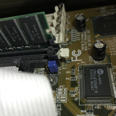
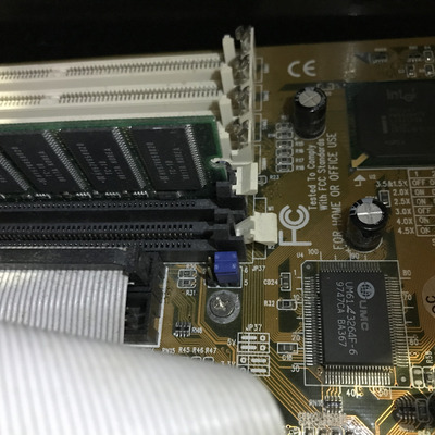
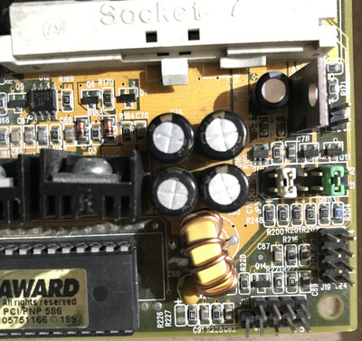
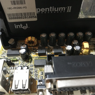
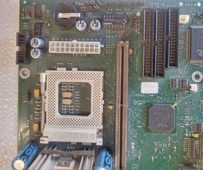
Here, looking at the circuit of the VCORE jumpers, of the 5BT5 Ver.2. X, a voltage of 3.3V is currently selected, because I use a Pentium 133 CPU, if I switch to a dual voltage CPU, I could get a lower voltage, maybe 2.6V?
Maybe yes, or maybe not, let's see if it's possible to understand something?
There are two methods to determine the exact voltage, one is mathematical, just make a calculation and you get the voltage, I am not an electronic technician, so I am not able to do this calculation, theoretically you should start from 3.3V and by resistance, you should get the value of the VCORE, which is definitely lower (I imagine yes ), the value of the resistance can be read from the photo (see SMD), but there could be a second resistance connected in some way, which could change the final result.
The other method, let's call it experimental, would be in practice this, before trying a dual voltage CPU, you can calculate from the +3.3V of the power supply, what resistance is needed to get to 2.6V, after several attempts you will find a value in OHm 🕉, but it could be completely useless, because in reality the voltage is not reduced directly by the +3.3V, but it comes from a Mosfet that has a VRef and a VOut (as well as a VIn), and therefore only at a certain VRef you get a VOut of 2.6V, so if you are capable, just do some simple calculations, otherwise (could we get angry?), we risk The CPU on duty, and we measure the voltages with the tester.
The risk that everything goes up in smoke, could be very low, already why risk the CPU, when you can do this measurement without the CPU on board, how do you do it ???
That's why I have to do some research, they could be fast, like not, as soon as I have news I'll update you.
AMD 286-16 287-10 4MB HD 45MB VGA 256KB
AMD 386DX-40 Intel 387 8MB HD 81MB VGA 256KB
Cyrix 486DLC-40 IIT387-40 8MB VGA 512KB
AMD 5X86-133 16MB VGA VLB CL5428 2MB and many others
AMD K62+ 550 SOYO 5EMA+ and many others
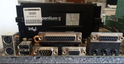
AST Pentium Pro 200 MHz L2 256KB