VOGONS


First post, by Nexxen

User metadata
Rank Oldbie
Rank
Oldbie

Hello!

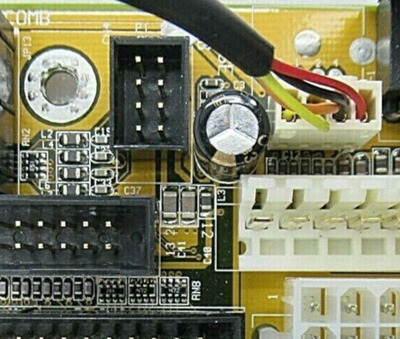
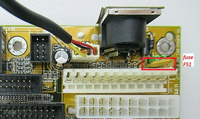
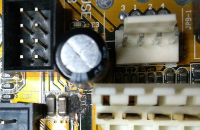
Said board has a burnt filter on the V line of the PS2 USB header.
I have no idea of the values I have to look for to buy a new piece of. The board works perfectly except for the PS2 header.
- solved by soldering everything together; suggestion of a 0.5A ferrite bead as a filter.

I was wondering, should I desolder the 4 pin header and solder a PS2 port to help speed up things or leave it as it is for "(fill the blank)" reason?
If I'm not wrong it's only for mouse support. Or maybe just any kind of PS2 device?
Edit: I withdrew the idea.

Any help is appreciated. 😀

https://www.gigabyte.com/Motherboard/GA-5AA/s … #support-manual

Edit: board has issues installing W2K with anything above K6-300, K6-2/iii makes it hang unless I fiddle like crazy with bios settings and results are inconsistent.
Random reboots arise.
With W98SE is more stable but hangs and reboots occasionally.

- solved: VRM caps faulty, soldered new caps and works 100%; probably K6-2 -iii, MII and 6x86 PR300 require higher cpu voltage stability that faulty caps couldn't provide.

Edit 2: Windows 2000 works but because of a bug only @ half FSB. W98 and Xp work @ full FSB

BIOS chip is Winbond W29C011A-15

Attachments

Last edited by Nexxen on 2021-07-08, 12:11. Edited 5 times in total.

PC#1 Pentium 233 MMX - 98SE
PC#2 PIII-1Ghz - 98SE/W2K

Reply 1 of 60, by snufkin

User metadata
Rank Oldbie
Rank
Oldbie

Found an ebay image of the board unburnt:

Unburnt_5aa.jpg
Filename
Unburnt_5aa.jpg
File size
120 KiB
Views
1157 views
File license
Fair use/fair dealing exception

Looks like as well as burnt surface tracks there's some burn marks on the PCB surface between the 'L3' silkscreen mark and the AT power connector, might indicate an internal track got a bit hot. Does the LPT port work ok? Component might be a ferrite bead a bit like this (don't know what the exact component spec should be): https://uk.farnell.com/murata/blm18ag331sn1d/ … 0603/dp/1515675 .

Reply 2 of 60, by Roman555

User metadata
Rank Oldbie
Rank
Oldbie
Nexxen wrote on 2021-06-18, 18:53:
Hello! […]
Show full quote

Hello!

Said board has a burnt filter on the V line of the PS2 header.
I have no idea of the values I have to look for to buy a new piece of. The board works perfectly except for the PS2 header.

I was wondering, should I desolder the 4 pin header and solder a PS2 port to help speed up things or leave it as it is for "(fill the blank)" reason?
If I'm not wrong it's only for mouse support. Or maybe just any kind of PS2 device?

Any help is appreciated. 😀

Hi!

Does a keyboard work? If MS and KB don't work both - find and check a fuse F1.
It seems the L3 filter (ferrite bead) is for a USB header power line. So burnt L3 causes no USB power .

The +5v for a mouse goes through L5.

If you have got a multimeter at hand you can check purpose of circuits and components and test them yourself.
It's easy! Turn off a PSU of a PC (unplug a power cord). Turn on a mulimeter into the diode mode. Set up pins of the multimeter on tested points.
The multimeter beeps if there's short circuit between tested points.

[ MS6168/PII-350/YMF754/98SE ]
[ 775i65G/E5500/9800Pro/Vortex2/ME ]

Reply 3 of 60, by Nexxen

User metadata
Rank Oldbie
Rank
Oldbie

I posted out of my notes but I didn't recheck anything.
Keyboard works, because I installed Win98 + at least one USB with mouse.

Guess I'll redo the check it all routine and post back later.

PC#1 Pentium 233 MMX - 98SE
PC#2 PIII-1Ghz - 98SE/W2K

Reply 4 of 60, by Nexxen

User metadata
Rank Oldbie
Rank
Oldbie

I just had to turn the page of my notebook to read that:

- it is connected to USB Vcc;
- upper connections fo the three smds are connected;
- lower part of the three smds, caps are connected, filter isn't (on its own to a resistance - 102 - third from the right of "RN8", below LPT)

Probably LPT doesn't get Vcc (good catch 😀), but USB should be working as it gets Vcc.
Could it be a filter just fore LPT?

Edit: I rechecked with a multimeter.

PC#1 Pentium 233 MMX - 98SE
PC#2 PIII-1Ghz - 98SE/W2K

Reply 5 of 60, by quicknick

User metadata
Rank Oldbie
Rank
Oldbie

Apart from the obvious damage, there's a short trace between the bottom of L3 and a via to its right and that looks burnt as well.
I'm guessing from that via there's an internal trace that goes to the +5V on the AT power connector, and that might be damaged as well as snufkin pointed out.
Any of the above would leave unpowered both the PS2 and the USB headers.
Simplest repair would be to provide +5V to the corresponding pins on the PS2 and USB headers, L3 can be bypassed with a wire link for testing purposes, just make sure the short that caused this is gone, you don't want further damage on there.

Reply 6 of 60, by Nexxen

User metadata
Rank Oldbie
Rank
Oldbie

L3 is connected to +5V, as PS2.
USB isn't.

In my notes, I used a PCI to USB 2.0 card 😀
L3 should be connected to the burnt smd, and it isn't.

I have to:
- replace the cap next to the burnt filter,
- put a new filter,
- do some L3 to filter soldering.

Anyone knows the values of those smd components?

PC#1 Pentium 233 MMX - 98SE
PC#2 PIII-1Ghz - 98SE/W2K

Reply 7 of 60, by Nexxen

User metadata
Rank Oldbie
Rank
Oldbie

Idk if it was caused by a short, I've seen filters go bad and burn.
I checked to see if there is anything around, but found nothing. Just a dead LPT and USB.

PC#1 Pentium 233 MMX - 98SE
PC#2 PIII-1Ghz - 98SE/W2K

Reply 8 of 60, by Roman555

User metadata
Rank Oldbie
Rank
Oldbie
quicknick wrote on 2021-06-19, 11:16:

Simplest repair would be to provide +5V to the corresponding pins on the PS2 and USB headers, L3 can be bypassed with a wire link for testing purposes, just make sure the short that caused this is gone, you don't want further damage on there.

Sorry, but it isn't a good piece of advice. Because there's a JP7 that switches power source :+5VSB or +5V.
So JP7 position "Close 1-2" directs voltage from +5VSB rail into KB and MS. It's better to just understand what's wrong now to not add more damages.
The good idea would be to clean burnt place proper to visually inspect damages of components and wires.

Attachments

  • ga_5aa_jp7.png
    Filename
    ga_5aa_jp7.png
    File size
    36.54 KiB
    Views
    1030 views
    File comment
    JP7 KB Power On (for ATX Power Supply only)
    File license
    CC-BY-4.0

[ MS6168/PII-350/YMF754/98SE ]
[ 775i65G/E5500/9800Pro/Vortex2/ME ]

Reply 9 of 60, by Roman555

User metadata
Rank Oldbie
Rank
Oldbie
Nexxen wrote on 2021-06-19, 11:26:
L3 is connected to +5V, as PS2. USB isn't. […]
Show full quote

L3 is connected to +5V, as PS2.
USB isn't.

In my notes, I used a PCI to USB 2.0 card 😀
L3 should be connected to the burnt smd, and it isn't.

I have to:
- replace the cap next to the burnt filter,
- put a new filter,
- do some L3 to filter soldering.

Anyone knows the values of those smd components?

Nexxen, just to make clear.
L3 is a burnt SMD. There isn't any other L3 on board. L3 is a filter (ferrite bead).
If you don't find proper replacement you can just buy a resistor zero OHm in a proper size (0805 in fact) for that purpose.

[ MS6168/PII-350/YMF754/98SE ]
[ 775i65G/E5500/9800Pro/Vortex2/ME ]

Reply 10 of 60, by Nexxen

User metadata
Rank Oldbie
Rank
Oldbie
Roman555 wrote on 2021-06-19, 14:23:
Nexxen, just to make clear. L3 is a burnt SMD. There isn't any other L3 on board. L3 is a filter (ferrite bead). If you don't […]
Show full quote
Nexxen wrote on 2021-06-19, 11:26:
L3 is connected to +5V, as PS2. USB isn't. […]
Show full quote

L3 is connected to +5V, as PS2.
USB isn't.

In my notes, I used a PCI to USB 2.0 card 😀
L3 should be connected to the burnt smd, and it isn't.

I have to:
- replace the cap next to the burnt filter,
- put a new filter,
- do some L3 to filter soldering.

Anyone knows the values of those smd components?

Nexxen, just to make clear.
L3 is a burnt SMD. There isn't any other L3 on board. L3 is a filter (ferrite bead).
If you don't find proper replacement you can just buy a resistor zero OHm in proper size (0805 in fact) for that purpose.

I was talking about the trace.
Where the trace ends there is no connection to where the old solder joint is (lower end of L3).
The solder joint is still there but the connection to the trace that goes to Vcc is dead.

If I put a solder blob or a copper wire it's just the same I assume.

PC#1 Pentium 233 MMX - 98SE
PC#2 PIII-1Ghz - 98SE/W2K

Reply 11 of 60, by Nexxen

User metadata
Rank Oldbie
Rank
Oldbie

The hole below L3 silkscreen goes to +5V on the m/b.

If you look at snufkin pic you can see that below the L3 marking there's a hole, that hole has a trace that goes to the lower end of "L3 SMD".
That doesn't connect to to where once was the lower end of the L3, I have to put some copper wire to connect them.

This filter acts for USB, goes through to USB ports, but doesn't look like it does any filtering to LPT as it goes straight to LPT.

Maybe usb vcc needs less noise?

PC#1 Pentium 233 MMX - 98SE
PC#2 PIII-1Ghz - 98SE/W2K

Reply 12 of 60, by Roman555

User metadata
Rank Oldbie
Rank
Oldbie
Nexxen wrote on 2021-06-19, 14:38:
The hole below L3 silkscreen goes to +5V on the m/b. […]
Show full quote

The hole below L3 silkscreen goes to +5V on the m/b.

If you look at snufkin pic you can see that below the L3 marking there's a hole, that hole has a trace that goes to the lower end of "L3 SMD".
That doesn't connect to to where once was the lower end of the L3, I have to put some copper wire to connect them.

This filter acts for USB, goes through to USB ports, but doesn't look like it does any filtering to LPT as it goes straight to LPT.

Maybe usb vcc needs less noise?

I understood now.
Yes, I agree. The burnt trace from the via (that is near L3) provided, protected by the FS1 fuse, +5V to circuits of USB (through L3 to power rail) and also to circuits of LPT (pull-up resistors).

[ MS6168/PII-350/YMF754/98SE ]
[ 775i65G/E5500/9800Pro/Vortex2/ME ]

Reply 13 of 60, by Nexxen

User metadata
Rank Oldbie
Rank
Oldbie

Below the burnt filter, which took away a hole layer, there is a GND trace.
I have to fill the hole, what should I use?

I was thinking that elevating the filter in order to avoid any contact (1mm from the mb).

I could put some solder on every single solder point and than add some copper wire.

I have a 1 µH smd, could that work???

PC#1 Pentium 233 MMX - 98SE
PC#2 PIII-1Ghz - 98SE/W2K

Reply 14 of 60, by Roman555

User metadata
Rank Oldbie
Rank
Oldbie
Nexxen wrote on 2021-06-19, 15:33:
Below the burnt filter, which took away a hole layer, there is a GND trace. I have to fill the hole, what should I use? […]
Show full quote

Below the burnt filter, which took away a hole layer, there is a GND trace.
I have to fill the hole, what should I use?

I was thinking that elevating the filter in order to avoid any contact (1mm from the mb).

I could put some solder on every single solder point and than add some copper wire.

I have a 1 µH smd, could that work???

Solder mask protects copper traces on PCB.
www.aliexpress.com/item/4000421028679.html
Personally I haven't used this technology yet.

If I were you I would
0) clean,
1) protect the GND trace of inner layer with an insulating tape,
2) not set up the L3 filter replacement at all,
3) make sure that the top pad of L3 not connected to GND,
4) connect necessary points soldering thin copper wire.

But all this is about the USB and not about PS/2 mouse.
Sorry, I maybe lost something. I didn't understand whether PS/2 mouse work or not now.

[ MS6168/PII-350/YMF754/98SE ]
[ 775i65G/E5500/9800Pro/Vortex2/ME ]

Reply 15 of 60, by Nexxen

User metadata
Rank Oldbie
Rank
Oldbie
Roman555 wrote on 2021-06-19, 18:56:
Solder mask protects copper traces on PCB. www.aliexpress.com/item/4000421028679.html Personally I haven't used this technology […]
Show full quote
Nexxen wrote on 2021-06-19, 15:33:
Below the burnt filter, which took away a hole layer, there is a GND trace. I have to fill the hole, what should I use? […]
Show full quote

Below the burnt filter, which took away a hole layer, there is a GND trace.
I have to fill the hole, what should I use?

I was thinking that elevating the filter in order to avoid any contact (1mm from the mb).

I could put some solder on every single solder point and than add some copper wire.

I have a 1 µH smd, could that work???

Solder mask protects copper traces on PCB.
www.aliexpress.com/item/4000421028679.html
Personally I haven't used this technology yet.

If I were you I would
0) clean,
1) protect the GND trace of inner layer with an insulating tape,
2) not set up the L3 filter replacement at all,
3) make sure that the top pad of L3 not connected to GND,
4) connect necessary points soldering thin copper wire.

But all this is about the USB and not about PS/2 mouse.
Sorry, I maybe lost something. I didn't understand whether PS/2 mouse work or not now.

It was my mistake, in my notes I was figuring out PS2 port connections.
I thought it was about PS2 port.

In fact I had figured out it was USB not working, along with LPT.
This happened because I used that board months ago and didn't read through my notes thoroughly.

Anyway I'm going to put some solder mask to be sure nothing happens.
And just solder copper wires.
Probably I'll remove the PS2 header and solder a PS2 connector. Much better.

PC#1 Pentium 233 MMX - 98SE
PC#2 PIII-1Ghz - 98SE/W2K

Reply 16 of 60, by snufkin

User metadata
Rank Oldbie
Rank
Oldbie
Roman555 wrote on 2021-06-19, 15:06:

The burnt trace from the via (that is near L3) provided, protected by the FS1 fuse

Ha, looks like L3 blowing protected the fuse then, I'd like to know what value that fuse is. There must have been several amps flowing to cause that much damage to L3 and surrounding tracks.

Sounds like a good suggestion to get the board cleaned up, protect exposed layers, then use wire to replace missing tracks. At least it sounds like the via is still connected, so the internal damage wasn't bad enough to crack the via. I think the filter is more about reducing EMC emissions from the computer (particularly high frequency noise), so it's probably good to have it, but things will probably still work if it's just replaced with a wire.

Reply 17 of 60, by quicknick

User metadata
Rank Oldbie
Rank
Oldbie
Roman555 wrote on 2021-06-19, 14:08:
quicknick wrote on 2021-06-19, 11:16:

Simplest repair would be to provide +5V to the corresponding pins on the PS2 and USB headers, L3 can be bypassed with a wire link for testing purposes, just make sure the short that caused this is gone, you don't want further damage on there.

Sorry, but it isn't a good piece of advice...

Actually I think it was, but maybe I should have explained better. Damn it, I was vague... 😁

Of course the quick and dirty way is to wire +5V directly to the relevant pin, so you can at least confirm if the USB/PS2/whatever is still working.

And of course you only do that if you haven't already repaired and replaced all the burnt/missing stuff, thus reinstating the original circuit.

Reply 18 of 60, by Roman555

User metadata
Rank Oldbie
Rank
Oldbie
snufkin wrote on 2021-06-19, 20:08:

Ha, looks like L3 blowing protected the fuse then, I'd like to know what value that fuse is. There must have been several amps flowing to cause that much damage to L3 and surrounding tracks.

Exactly 😁 Good point!
Also some type of fuses can recover their ability to conduct current. I don't know the value and whether or not it is such type.

Nexxen wrote on 2021-06-19, 19:31:

Anyway I'm going to put some solder mask to be sure nothing happens.
And just solder copper wires.
Probably I'll remove the PS2 header and solder a PS2 connector. Much better.

I wish you good luck! I hope you'll successfully repair this good mainboard.

Attachments

[ MS6168/PII-350/YMF754/98SE ]
[ 775i65G/E5500/9800Pro/Vortex2/ME ]

Reply 19 of 60, by Nexxen

User metadata
Rank Oldbie
Rank
Oldbie

Guys, thank you for the help!
The fuse didn't blow, still there and looks good. Not shorted either.

I had an iMac G4 screen go black. Working with ext vga but no screen. Checked wires, nothing wrong; but Vcc was wrong, and it was a filter that went bad with a reading of ≃ 900 ohms instead of 0.06. It fried its surroundings.
Removed and replaced with a huge solder blob and screen was back on 100% working.
On another m/b I had Vcc issues and again a filter that went bad with high ohm reading.
I guess they go bad in time, especially if they are inductors (they dissipate to heat and can be very high temp; just learnt on wiki so don't shoot me).

I wrote stuff as I was going, so much confusion and I apologize.

I have more stuff to repair thus expect more threads to come.

PC#1 Pentium 233 MMX - 98SE
PC#2 PIII-1Ghz - 98SE/W2K