VOGONS


386 motherboard > 1MB / A20 woes

Topic actions

First post, by FrankieKat

User metadata
Rank Newbie
Rank
Newbie

I just unearthed a time capsule , which is my old AMD 40MHz 386 PC from the early 90's. This was my own PC on which I spent (wasted) untold hours of my youth on EGA/VGA games and BBS fun. It has been sitting in a climate-controlled basement almost untouched for the last 25 years, complete in original case with 4MB RAM, a ET4000 VGA card and a 200MB IDE drive. There is one problem though...

When the PC is booted cold, after being off for some period of time (between 25 years and maybe 10 minutes), everything boots up fine. However, after a power off/on (without waiting long) or a front panel hard-reset (anything that triggers the BIOS to count RAM basically) it then only sees the first 1MB of RAM (CMOS memory size mismatch)... until it it fully shut off for at least 5-10 minutes. A "soft" ctrl-alt-delete after the first (good) boot does not trigger the issue and will continue to work fine with all of the RAM. Powering off the PC and powering it back on right away it will only see 1MB unless it's powered off for the 5-10 mins.

Facts/clues:

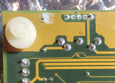
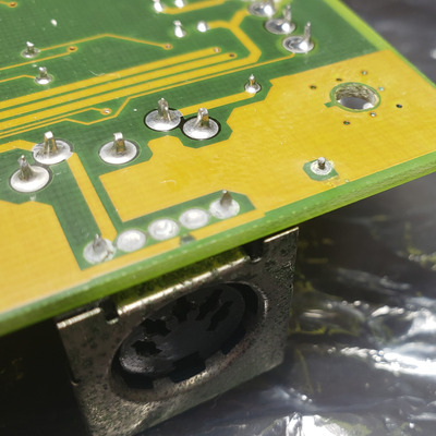
1. Original soldered NiCd CMOS battery was previously removed, though there seems to be a very small amount of battery leakage evidence on the board mostly around the keyboard connector area. I cleaned it well with vinegar and 91% iso and I don't see any obvious damage to traces. I have not pulled the board out of the case to inspect the underside though. I can't imagine this PC was touched in the last 25 years so the battery must have been removed prior to storage (someone deserves a free burrito for that).
2. Have tried different RAM (4 x 1MB SIMMs), and problem doesn't change. If 8MB (8 x 1MB SIMMs) is installed, the issue is the same - it will see 8MB on first cold boot and then only the first 1MB on "hard" reboot. Installing 1MB of RAM (4 x 256K) works as expected.
3. All of the RAM tests fine in another 386SX PC I have using the long test in Checkit 3. That PC does not exhibit this problem.
4. When all RAM is seen computer it completely stable, no crashes or lockups in Windows or 386 mode games that utilize EMS/XMS memory. Likewise the PC is completely stable when it only sees the 1MB of RAM.
5. I connected 3 x 1.5V AA batteries to the external (4 pin) battery connectors and that makes no difference, other than it now remembering CMOS settings. The RTC however is not particularly accurate (it gained about 4 hours sitting for 12 hours turned off).
6. The hardware configuration is unchanged since it was put away ~25 years ago when it worked fine, so wouldn't be related to any "incompatibilities" of parts added/changed.

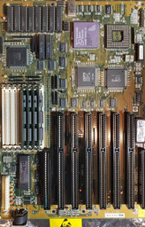
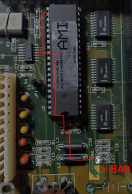
The board is an MSI MS-3121 ver 3.0, AMD 386/40MHz (image), 64KB cache (PeakD/M). I do not have any original manuals for it, nor can I find scans online, though it is a very close relation to this and this.

Has anyone ever encountered anything like this, and any ideas what kind of fault this might be, and of course, is there a chance of repairing?

Thanks!

FK

Last edited by FrankieKat on 2021-07-26, 18:23. Edited 2 times in total.

Reply 1 of 27, by mR_Slug

User metadata
Rank Member
Rank
Member

In my head i'm thinking "gate A20". Can't remember the exact details but IIRC the keyboard controller has a trace routed to it to do with memory. Perhaps someone with more knowledge can elaborate. Can you remove the keyboard controller and reinsert it? also check traces under it for battery damage.

The Retro Web | EISA .cfg Archive | Chip set Encyclopedia

Reply 2 of 27, by FrankieKat

User metadata
Rank Newbie
Rank
Newbie

After doing some more testing I have some new information. Apparently when I ran DOS memmaker it added /M:2 to the HIMEM.SYS line in config.sys, which looking at the previous versions did not have the switch, which exists as a workaround to inconsistent motherboard implementations of the A20 line. I did some experimentation and here's what happens for each /M value on HIMEM.SYS:

(no /M): "Unable to control A20 line"
/M:1 : "HIMEM.SYS has detected unreliable XMS memory at address 0010000h" and only 1MB of RAM is seen by BIOS even with ctrl-alt-delete
/M:2 : The behavior described in the original post
/M:3 : Hard lock up after Starting MS-DOS...
/M:4 : same as /M:1

I haven't been able to test 5-15 since once it stops seeing >1MB I have to stop and let it settle. However, since it used to work fine with no /M switch at all, testing these doesn't matter. I'd also think that the /M:1 and /M:4 memory errors are a red herring since the computer is completely stable using extended memory (when it sees it) so doesn't feel like a physical memory error issue.

mR_Slug wrote on 2021-06-20, 18:43:

In my head i'm thinking "gate A20". Can't remember the exact details but IIRC the keyboard controller has a trace routed to it to do with memory. Perhaps someone with more knowledge can elaborate. Can you remove the keyboard controller and reinsert it? also check traces under it for battery damage.

I removed the 8042 (AMI ROM) keyboard controller, cleaned the pins and re-inserted and no change. Upon closer inspection though, the corrosion near the keyboard/battery area I see doesn't quite look like the telltale varta battery damage, it's almost more like garden variety corrosion from moisture and dust possibly due to the keyboard jack more open and exposed directly to elements.

As for the A20 line, if I'm understanding correctly basically the PC/BIOS uses a keyboard interface output pin to control one input of a gate that's between the CPU address lines and the bus lines, effectively allowing a software-controlled switch to mask off (make always 0) the highest bit of the address that the CPU can put on the bus. Looking at the IBM AT technical reference (unlikely to find a schematic for this actual motherboard) , one input on the gate is connected to address 20 from the CPU, the second input is tied low and the select pin (pin 1) tied to P21 (pin 22) on the 8042. And if I'm reading it right it means that the select pin must be LOW in order to "pass through" the output of A20 from the CPU, otherwise it will always output 0 (at least on the 5170 implementation).

Now if I probe pin 22 on the 8042, it is high during the memory count and then goes low and stays low. It does not appear to go high again (that I can tell) between POST and boot. This board does not have a "Fast A20" option in the BIOS or any jumpers or markings to that effect. If the 8042 "A20" pin is high, meaning high memory access is disabled, why would it go high during the BIOS memory check? That would seem to disable high memory access, meaning the BIOS might be testing the same (low) memory 4 times. Again, can't be 100% sure this is how it works because I'm basing that off of the 5170 schematic, however if the pin is low while the OS is running and can see all RAM fine it would seem to imply that low is the correct state. This is all to say, the output of the 8042 seems a bit inconclusive. Since the BIOS is consistently taking it high and low, there's not a short.

Any other thoughts or ideas would be greatly appreciated!

Thanks,
FK

Last edited by FrankieKat on 2021-06-21, 21:26. Edited 1 time in total.

Reply 3 of 27, by mR_Slug

User metadata
Rank Member
Rank
Member

I'm not sure about tying the pin directly to ground. The line should have either a resistor to pull it high or one to pull it low. If it has one somewhere to pull it low, then to pull it high,the motherboard connects it directly to 5V. If this is the case, pulling it directly to ground without a resistor would create a dead short between GND and 5V when the motherboard tries to pulls it high.

That's about all i know. I guess you could try to see it there is resistance between the pin and 5V and between the pin and GND to determine where the pull-up/pull-down resistor is, but I'm not sure if that is conclusive. I don't know enough about TTL to say one way or another.

The Retro Web | EISA .cfg Archive | Chip set Encyclopedia

Reply 4 of 27, by FrankieKat

User metadata
Rank Newbie
Rank
Newbie
mR_Slug wrote on 2021-06-21, 20:25:

I'm not sure about tying the pin directly to ground. The line should have either a resistor to pull it high or one to pull it low. If it has one somewhere to pull it low, then to pull it high,the motherboard connects it directly to 5V. If this is the case, pulling it directly to ground without a resistor would create a dead short between GND and 5V when the motherboard tries to pulls it high.

That's about all i know. I guess you could try to see it there is resistance between the pin and 5V and between the pin and GND to determine where the pull-up/pull-down resistor is, but I'm not sure if that is conclusive. I don't know enough about TTL to say one way or another.

Thanks -- was just a thought, probably not something to worry about just yet. The resistance the 8042 between pin 21 and Vss (GND) is ~3.9k, and ~4.7k between pin 21 and C5 (address bit 20) on the ISA bus slot (all cards removed).

Reply 5 of 27, by FrankieKat

User metadata
Rank Newbie
Rank
Newbie

I took a fresh look at this again and learned a few new things.

Recap:

1. When PC boots cold (from being off for a while) the BIOS memory check will sometimes see all all 8MB of RAM and sometimes only sees 1MB. I'm not sure if this correlates to state of the PC when it was shut down, but I'll try to test that theory.
2. Generally if it sees 8MB, a "soft" reboot (ctrl-alt-delete) will almost always allow it to continue seeing all of the RAM.
3. Pressing the reset button, will almost always make it only see 1MB.
4. HIMEM.SYS only works with /M:2 parameter. Otherwise will say "unreliable memory", "cannot control A20 gate" or just simply lock up
5. No reliability or program crashing issues. Protected mode (Windows 3.1, Simcity 2000) or EMS (Ultima Underworld) are 100% stable.
6. BIOS has no "Fast A20" gate option in settings.
7. Keyboard controller 8042 has been removed, pins cleaned and re-seated... no change.
8. Motherboard is an MSI MS-3121 ver 3.0, AMD 386/40MHz with AMI BIOS dated 05/05/91.

New info:

As everything still seems to point back to A20, here's the result of some troubleshooting from OSDev.org.

1. If, after the PC only sees 1MB, I run this Fast A20 enable code and soft reboot (ctrl-alt-del), the BIOS will count/see all 8MB again and will usually work fine until a hard reboot. Also, running this A20 line testing program will return 1 indicating A20 enabled after running the Fast_A20 code, whereas it would return a 0 before. Running Checkit 3 shows that A20 is Active after run as well.
2. The INT 15 method to enable A20 fails (CF set) meaning "INT 15h is not supported".
3. The 0xEE method has no effect.
4. Using the Keyboard Controller method, will make pin 22 on the 8042 keyboard controller go high. Otherwise it is always low, even if step 1 is done. Unfortunately, this code does not seem to re-enable my keyboard after this is run, so I can't investigate much more after this. All that I can do after is hard reset (which will make high memory not seen again).

The fact that the Fast A20 gate code works and temporarily "heals" the problem seems to further support the A20 line as being suspect. It uses a CHIPS integrated chipset with fewer discrete/passive components, which are nearly all SMT so not so much stuff to trace or test. Since I know the PC used to work in it's current hardware configuration, it points to a fault in a component since it was actively used.

Would really appreciate any thoughts, experience or ideas if anyone has ever seen anything like this before.

FK

Last edited by FrankieKat on 2021-07-27, 18:08. Edited 1 time in total.

Reply 6 of 27, by Horun

User metadata
Rank l33t++
Rank
l33t++

Can you post a better picture of your board ? The one in your first post is hard to see/read to check for damage/oddities/etc.

Hate posting a reply and then have to edit it because it made no sense 😁 First computer was an IBM 3270 workstation with CGA monitor. Stuff: https://archive.org/details/@horun

Reply 9 of 27, by FrankieKat

User metadata
Rank Newbie
Rank
Newbie
Horun wrote on 2021-07-27, 00:57:

Can you post a better picture of your board ? The one in your first post is hard to see/read to check for damage/oddities/etc.

That pic wasn't my actual board, it was just an identical pic I found online, so I pulled the board and got pics.

At first glance on the bottom side, it appears that there are some dodgy solder joints in the top left, however after cleaning them off and touching them up they really aren't a problem. I'm actually having a difficult time telling where the outside end of that L1 inductor (the dodgy joint) goes, since I cannot visually see the trace from either side and the inductor value is so low that it just reads as continuity on my DVM, I can't probe around and be sure I'm tracing the right end. However, a spot check of random traces that I can see all check out... I haven't found any bad traces on the board.

However, upon close inspection the keyboard DIN connector appears to have come a bit loose from the board and looking closely in the picture you can see that it's broken away from the grounding lugs to the shield. I tested it and indeed, the DIN's ground has been broken, though will make contact if pressure is put on it. Could a bad ground to the keyboard possibly be the cause here? (yes, I know the answer to that question is... "well make the repair and see if that fixes it"...). Seems too easy though! I'll re-assemble and see if it makes any difference...

FK

Attachments

Reply 10 of 27, by mkarcher

User metadata
Rank l33t
Rank
l33t
FrankieKat wrote on 2021-07-26, 22:22:

The fact that the Fast A20 gate code works and temporarily "heals" the problem seems to further support the A20 line as being suspect. It uses a CHIPS integrated chipset with fewer discrete/passive components, which are nearly all SMT so not so much stuff to trace or test.

It seems like the fast A20 gate (internal to the chipset) works, but AT keyboard controller A20 gate is unreliable. Using /M:2 forces HIMEM to use the fast A20 gate

To me this looks like the trace from the keyboard A20 gate pin to the chipset A20 gate input being interrupted. The chipset thus receives a random signal instead of the signal originating from the keyboard controller. You should be able to find the datasheet for your CHIPS chipset, to find out where the keyboard controller A20 gate pin should be connected to.

Reply 11 of 27, by FrankieKat

User metadata
Rank Newbie
Rank
Newbie
mkarcher wrote on 2021-07-27, 09:02:

To me this looks like the trace from the keyboard A20 gate pin to the chipset A20 gate input being interrupted. The chipset thus receives a random signal instead of the signal originating from the keyboard controller. You should be able to find the datasheet for your CHIPS chipset, to find out where the keyboard controller A20 gate pin should be connected to.

Makes sense. I know for sure that the 8042 A20 gate pin connects to one of the inputs on the the DM7406 inverter/buffer gate, though the multilayered PCB makes it a little trickier to trace onward. I'll keep poking at it and also see.

No luck finding a datasheet online yet. Does anyone have a good source for datasheets for these (CHIPS F82C351 B-1, F82C355 A, F82C356)?

Thanks!

FK

Reply 12 of 27, by mkarcher

User metadata
Rank l33t
Rank
l33t
FrankieKat wrote on 2021-07-27, 12:45:

No luck finding a datasheet online yet. Does anyone have a good source for datasheets for these (CHIPS F82C351 B-1, F82C355 A, F82C356)?

The set of these three chips is called the CHIPSet CS82310, with the marketing name PEAK/DM. You can find an extensive data book e.g. at the location I linked. /GATE_A20 input is pin 36 of the 82c351.

Reply 13 of 27, by Deunan

User metadata
Rank Oldbie
Rank
Oldbie
FrankieKat wrote on 2021-07-27, 12:45:

Makes sense. I know for sure that the 8042 A20 gate pin connects to one of the inputs on the the DM7406 inverter/buffer gate, though the multilayered PCB makes it a little trickier to trace onward. I'll keep poking at it and also see.

You sure you are tracing the correct signal? Typically the KBC stuff that is connected to '06 gates is the keyboard data and clock lines. And these are of no interst to you - neither is the actual keyboard, it's cable or plug and connector state, unless it's some very obvious short that just prevents the 8x42 from working at all. Which is unlikely because the '06 there is to isolate KBC ports from actual connector pins and it's OC gates with pull-ups so frankly as short-resistant as it gets.

Typically the A20 gate signal on KBC is pin 22. I would not be surprised to find it not connected at all, or perhaps just to the CPU socket. 386 doesn't need that signal but DLC/SLC 486 from Cyrix wants to have it - though it can be worked around. Usually a caching chipset will do A20 masking internally because that is required for correct cache operation - though I suppose it can also have an input routed from KBC to be aware of any older program trying to mess about with it via 8x42. You'd think that is the way to go but no, I have seen mobos that just ignore any A20 signals from KBC, only the fast method is working properly on those mobos.

BTW which code path (C or ASM) are you using to flip the KBC gate? Try something like this:

void init_A20(void)
{
uint8_t a;

disable_ints();

kyb_wait_until_done();
kyb_send_command(0xD0); // Read from input

kyb_wait_until_done();
a=kyb_get_data();

kyb_wait_until_done();
kyb_send_command(0xD1); // Write to output

kyb_wait_until_done();
kyb_send_data((a & 0xCD) | 0x12);

enable_ints();
}

Reply 14 of 27, by FrankieKat

User metadata
Rank Newbie
Rank
Newbie
mkarcher wrote on 2021-07-27, 09:02:

To me this looks like the trace from the keyboard A20 gate pin to the chipset A20 gate input being interrupted. The chipset thus receives a random signal instead of the signal originating from the keyboard controller. You should be able to find the datasheet for your CHIPS chipset, to find out where the keyboard controller A20 gate pin should be connected to.

Well, good work Eagle Eyes! I've confirmed that the trace that comes from the output of the A20 pin inverter is open in that area right by the battery. From there I traced it to pin 36 on the 82c351. So looks like I need to repair that trace (never worked on a SMT board like this, but I'm sure YouTube will help me there).

Thank you - and will post an update soon.

FK

Attachments

Reply 15 of 27, by jakethompson1

User metadata
Rank Oldbie
Rank
Oldbie
FrankieKat wrote on 2021-07-27, 16:32:

Well, good work Eagle Eyes! I've confirmed that the trace that comes from the output of the A20 pin inverter is open in that area right by the battery. From there I traced it to pin 36 on the 82c351. So looks like I need to repair that trace (never worked on a SMT board like this, but I'm sure YouTube will help me there).

Don't people often just add a "bypass" wire on the underside of the board?

I was kind of wondering if your issue could have been heat-related given that it goes away if you leave it shut down. But perhaps not. I have some old AT-era computer repair books that got into that stuff like taking infrared pictures of the board and spraying it during operation (probably with something environmentally nasty like freon?) as a way to troubleshoot intermittent problems.

Reply 16 of 27, by mkarcher

User metadata
Rank l33t
Rank
l33t
FrankieKat wrote on 2021-07-27, 16:32:

Well, good work Eagle Eyes! I've confirmed that the trace that comes from the output of the A20 pin inverter is open in that area right by the battery. From there I traced it to pin 36 on the 82c351. So looks like I need to repair that trace (never worked on a SMT board like this, but I'm sure YouTube will help me there).

In such cases, I usually scratch the solder mask from the copper traces on both sides of the break, and solder a thin strand of copper wire over the break, and fix/isolate the bodge with nail polish.

Reply 17 of 27, by mkarcher

User metadata
Rank l33t
Rank
l33t
jakethompson1 wrote on 2021-07-27, 16:46:

I was kind of wondering if your issue could have been heat-related given that it goes away if you leave it shut down. But perhaps not.

In this case, the input is an open CMOS pin, which can read high or low influenced by minimal amounts of stray charge that can be caused by leakage currents. I don't think it is heat related, but the time when the computer is shut down allows some stray charge to drain from the /GATE_A20 pin.

Reply 18 of 27, by jakethompson1

User metadata
Rank Oldbie
Rank
Oldbie
mkarcher wrote on 2021-07-27, 16:53:
jakethompson1 wrote on 2021-07-27, 16:46:

I was kind of wondering if your issue could have been heat-related given that it goes away if you leave it shut down. But perhaps not.

In this case, the input is an open CMOS pin, which can read high or low influenced by minimal amounts of stray charge that can be caused by leakage currents. I don't think it is heat related, but the time when the computer is shut down allows some stray charge to drain from the /GATE_A20 pin.

Ah, so it's the same reason unused i/o needs a pull up or pull down resistor? I wish I had taken some electronics or computer engineering courses because my theoretical knowledge in this area is nil...

Reply 19 of 27, by FrankieKat

User metadata
Rank Newbie
Rank
Newbie
Deunan wrote on 2021-07-27, 16:29:
FrankieKat wrote on 2021-07-27, 12:45:

Makes sense. I know for sure that the 8042 A20 gate pin connects to one of the inputs on the the DM7406 inverter/buffer gate, though the multilayered PCB makes it a little trickier to trace onward. I'll keep poking at it and also see.

You sure you are tracing the correct signal? Typically the KBC stuff that is connected to '06 gates is the keyboard data and clock lines. And these are of no interst to you - neither is the actual keyboard, it's cable or plug and connector state, unless it's some very obvious short that just prevents the 8x42 from working at all. Which is unlikely because the '06 there is to isolate KBC ports from actual connector pins and it's OC gates with pull-ups so frankly as short-resistant as it gets.

Typically the A20 gate signal on KBC is pin 22. I would not be surprised to find it not connected at all, or perhaps just to the CPU socket. 386 doesn't need that signal but DLC/SLC 486 from Cyrix wants to have it - though it can be worked around. Usually a caching chipset will do A20 masking internally because that is required for correct cache operation - though I suppose it can also have an input routed from KBC to be aware of any older program trying to mess about with it via 8x42. You'd think that is the way to go but no, I have seen mobos that just ignore any A20 signals from KBC, only the fast method is working properly on those mobos.

Yeah, I've triple checked the path and it goes from 8042 Pin 22 -> 7406 inverter Pin 3 (A2) -> F82C351 Pin 36, and there IS a damaged trace between 7406 and F82C351, which confirm's mkarcher's reply too.

It does seem strange that the KBC A20 line would come into use since the board obviously supports Fast A20. Perhaps the BIOS uses only the 8042 A20 line for it's memory test and RAM sizing, and the OS is free to use the Fast A20 if it want. This seems like it actually explains the behavior, where a soft reset does not reset the Fast A20 whereas a hardware reset does. The BIOS enables KBC A20 (which doesn't work) but since the Fast A20 is still enabled it sees the RAM (for now). HIMEM first attempts KBC A20, which fails unless /M:2 (Fast A20) is forced. The pulldown (or is it a pullup) resistor between the 7406 and C351 is on the 7406 side of the broken trace, meaning the C351's A20 pin is left floating which could easily explain the inconsistent behavior and perhaps why it sees all of the RAM after the PC has been off for a while.

Okay, I'm off to attempt repair on that trace. Seems like a lot more of a smoking gun than the flakey keyboard ground too.

Thx!

FK

Also - I used the ASM code when testing the A20. I'll try again once those two connections are fixed and see if that makes a difference.

Last edited by FrankieKat on 2021-07-27, 18:07. Edited 1 time in total.