I have a Tandy 1000EX without the external floppy drive.
Is there any pinout diagram? I could only find an internal drive pinout.
I want to see if I can create an adapter cable for it
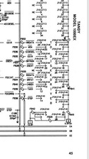
There's a section on floppy drives that looks useful, and in particular it gives the pins on the tandy connector that carry power. +5V on 3,5,7,9,11 and +12V on 29,31,33.
[editing to add the following after realising I misunderstood...]
I'm not certain about the DSEXT and BMTRON and how they map to the Drive Select and Motor On pins. I also think that the pin 2 input to a standard floppy probably wants to be grounded. Doesn't look like there's a disk change or ready signal.
I also did the mapping, turned out to be same as yours.
On internal side, DS wire is connected to DS0 of internal drive, externally we should also connect it pin selected by drive (e.g. DS1 for DS1-set drive).
I will order some 30 pin edge and 34 pin ide connectors then will make a prototype on perfboard and maybe make a PCB later.
There's a section on floppy drives that looks useful, and in particular it gives the pins on the tandy connector that carry power. +5V on 3,5,7,9,11 and +12V on 29,31,33.
[editing to add the following after realising I misunderstood...]
I'm not certain about the DSEXT and BMTRON and how they map to the Drive Select and Motor On pins. I also think that the pin 2 input to a standard floppy probably wants to be grounded. Doesn't look like there's a disk change or ready signal.