VOGONS


First post, by nuno14272

User metadata
Rank Member
Rank
Member

Hello everyone.
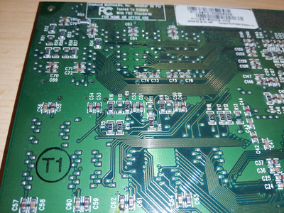
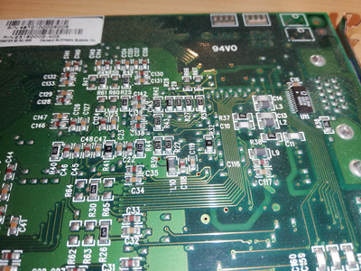
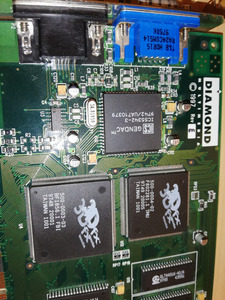
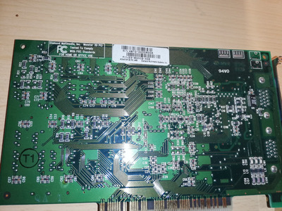
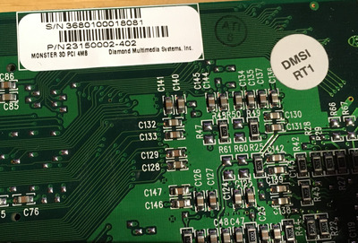
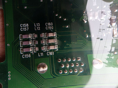
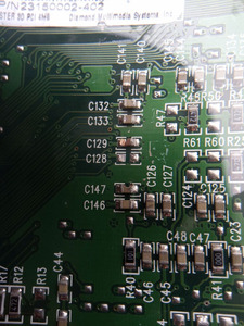
I've just find a Diamond 3D (3DFX - Voodoo1 ) in a srapt yard. The card in general looks good, but in the back, theres a few smd caps that have been torn apart.

I need your help to find out what are the values.

it's the: C128, C129, C147, L11, L12, L13

93WPPpx
f4Jy6Yb

Thank you..

Attachments

1| 386DX40
2| P200mmx, Voodoo 1
3| PIII-450, Voodoo 3 3000

Reply 1 of 11, by Eep386

User metadata
Rank Member
Rank
Member

Judging by the L11 ~ L13 indicators, those aren't SMD caps but rather surface mount inductors or ferrite beads.
C28 and C29 are caps though, and in pretty rough shape at that.

Unfortunately your guess is as good as mine as to the precise values of the components used. 🙁

Life isn't long enough to re-enable every hidden option in every BIOS on every board... 🙁

Reply 2 of 11, by snufkin

User metadata
Rank Oldbie
Rank
Oldbie

Unless someone's got a card they can take the components off to measure, my guess is L11-13 are noise filters for the monitor ID DDC signals (based on where they go on the 15 pin connector that I'm assuming is a VGA output). May work with them shorted, or maybe try something in the 1 - 10 uH range. Capacitors might be decoupling of some sort (one side goes to the big copper area that's probably ground), perhaps around 1uF.

Reply 3 of 11, by nuno14272

User metadata
Rank Member
Rank
Member

I've been told that the caps are always in double, so if one of them is good, the other will be the same measurement. IS THIS CORRECT?

The C147 i can tell the value by looking at C146

The C128 and C129, i'm out of luck because they are bad or missing.

The L11, L12, L13, no idea what they where.. Thanks Eep386 for the hint.. I have ferrite beds..

I will try and see.

1| 386DX40
2| P200mmx, Voodoo 1
3| PIII-450, Voodoo 3 3000

Reply 5 of 11, by snufkin

User metadata
Rank Oldbie
Rank
Oldbie
nuno14272 wrote on 2021-09-09, 08:48:

I've been told that the caps are always in double, so if one of them is good, the other will be the same measurement. IS THIS CORRECT?

That may not be true. I know it was a design guide from years ago to have a range of capacitance for decoupling caps as it helps smooth out a greater frequency range, so you might have 0.1uF, 1uF and 10uF near to power pins of chips (putting smallest values closest).

PlanetAnalog wrote:

Frequently, in the lab and under time pressure, capacitors are copiously added until the needed circuit performance appears. Which capacitors should you add and why? Identical values of capacitance placed in parallel will just lower the impedance value uniformly versus frequency. Different values of capacitance will broaden the bandwidth where low impedance appears, provided that you attend to the issues we’re about to cover. Otherwise, it could be a case of more definitely being less!

from https://www.planetanalog.com/know-the-sometim … bypass-network/#

Diagrams don't seem to be working on that article, but there are some here: https://electronics.stackexchange.com/questio … itors-come-from

Reply 6 of 11, by Jo22

User metadata
Rank l33t++
Rank
l33t++

I do have a Diamond Monster 3D, too!

I can do a few measurements, if really needed.. But desoldering is no option.

Anyway, I'm willing to do some tests.
The result will be very crude, though. 🙁

Edit: I did some measuring..
C128.. 3,3 nF
C129.. 6 nF
C146.. 6 nF
C147.. 6 nF

But please take these values with a grain of salt.
Measuring in-circuit/in-system produces not correct results.
Lifting at least one leg of a capacitor/resistor is the better way of doing it. 😀

Attachments

Last edited by Jo22 on 2021-09-10, 06:21. Edited 1 time in total.

"Time, it seems, doesn't flow. For some it's fast, for some it's slow.
In what to one race is no time at all, another race can rise and fall..." - The Minstrel

//My video channel//

Reply 8 of 11, by Thermalwrong

User metadata
Rank Oldbie
Rank
Oldbie

I pulled off those caps and soldered them onto the component tester, they went back pretty nicely 😀

IMG_1207.JPG
Filename
IMG_1207.JPG
File size
898.98 KiB
Views
454 views
File license
CC-BY-4.0

It makes me wonder if there could be a cap map for the Voodoo 1 reference cards like the Voodoo 2 cards have.
Here are the readings I got:
c128 = 57nf? (a value 10% + or -)
c129 = 9000pf (or a 1nf 10%-rating)
c146 = 100nf (10%)
c147 = 10nf

Edit: I pulled off one inductor to check its value but couldn't get a reading for it other than as a resistor? So Eep386's suggestion is good, or see if dead video cards / igp motherboards have similar

Last edited by Thermalwrong on 2021-09-09, 23:14. Edited 1 time in total.

Reply 10 of 11, by ChrisK

User metadata
Rank Member
Rank
Member

The "L"-parts usually are ferrite beads for filtering high-frequency noise for EMC compliance.
They are spec'ed with an impedance value at a specific frequency, e.g. 600 Ohms @ 100 MHz.
With DC current they ideally shall have zero Ohms but practically they have a few Ohms.
With rising frequency their impedance rises. So if your signal is 10 MHz max. you want the ferrite to have low impedance up until there so that your signal can pass. On the opposite, higher frequency noise will be blocked.
So, the first key spec is the current carrying capability followed by an impedance value for blocking unwanted noise. There are different characteristics for different use case (LF/HF signals, power, ...).

For this case some 10s or maybe 100 mA should be sufficient along with an impedance of 100-600 Ohms.
The exact original value won't be measureable until someone has specific measuring gear such as an Keysight E4991A impedance analyzer.

Reply 11 of 11, by nuno14272

User metadata
Rank Member
Rank
Member
Thermalwrong wrote on 2021-09-09, 22:48:
I pulled off those caps and soldered them onto the component tester, they went back pretty nicely :) IMG_1207.JPG […]
Show full quote

I pulled off those caps and soldered them onto the component tester, they went back pretty nicely 😀
IMG_1207.JPG

It makes me wonder if there could be a cap map for the Voodoo 1 reference cards like the Voodoo 2 cards have.
Here are the readings I got:
c128 = 57nf? (a value 10% + or -)
c129 = 9000pf (or a 1nf 10%-rating)
c146 = 100nf (10%)
c147 = 10nf

Edit: I pulled off one inductor to check its value but couldn't get a reading for it other than as a resistor? So Eep386's suggestion is good, or see if dead video cards / igp motherboards have similar

THANK YOU.... really.. THANK YOU..
Gona replace/install de caps with the closer values and test it...

replay to it later

1| 386DX40
2| P200mmx, Voodoo 1
3| PIII-450, Voodoo 3 3000