VOGONS


First post, by waterbeesje

User metadata
Rank Oldbie
Rank
Oldbie

Recently I've bought some parts to build a s7 Pentium system. The motherboard is a FIC PA-2005 and is working (just past bios post for now).
http://www.win3x.org/uh19/motherboards/2420

Still work in progress, but I need some advice to get on.

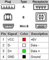
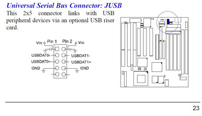
On the motherboard there is a USB connector. I'd love to connect it, but it's not clear to me if the pinout is straight forward.

Can anybody confirm if I connect pin 1 to red it's fine? Or will that turns into magic smoke? Changing pins is easy, but I need to know for sure.

CameraZOOM-20210905223731596.jpg
Filename
CameraZOOM-20210905223731596.jpg
File size
305.98 KiB
Views
1039 views
File license
CC-BY-4.0
CameraZOOM-20210905223643947.jpg
Filename
CameraZOOM-20210905223643947.jpg
File size
316.42 KiB
Views
1039 views
File license
CC-BY-4.0

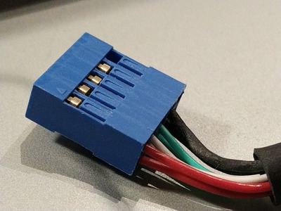
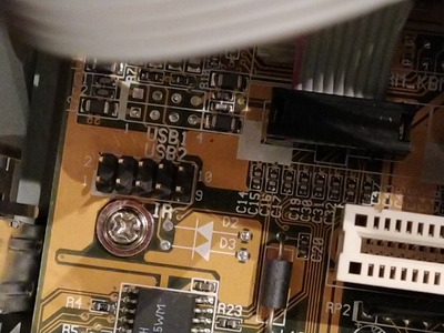
The blue connector has the same colour eiers next to eachother. There was the obvious blocked pin, but I've opened it to make the connector fit onto the 10p motherboard connectoto
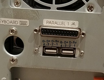
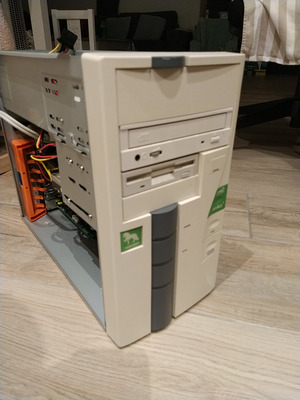
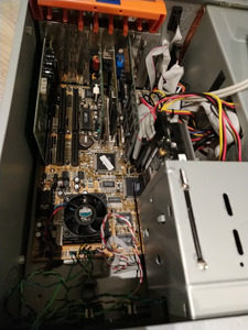
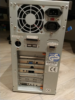
Some bonus pics:

CameraZOOM-20210905224206751.jpg
Filename
CameraZOOM-20210905224206751.jpg
File size
260.06 KiB
Views
1039 views
File license
CC-BY-4.0
CameraZOOM-20210905224226703.jpg
Filename
CameraZOOM-20210905224226703.jpg
File size
336.34 KiB
Views
1039 views
File license
CC-BY-4.0
CameraZOOM-20210905224241795.jpg
Filename
CameraZOOM-20210905224241795.jpg
File size
346.8 KiB
Views
1039 views
File license
CC-BY-4.0

Stuck at 10MHz...

Reply 1 of 17, by Horun

User metadata
Rank l33t++
Rank
l33t++

Here is the pin out of the FIC VA-503+. small reds should go to pins 1 and 2, the small black grounds should go to pins 7 & 8 and if it has a second set of blacks they go to 9 & 10 if it is the same but double check the +5v and Ground with a Digi meter to make sure.
The green and white should be USB + and - but double check with the front panel to see which is which.
edit: better USB picture...

Attachments

  • USB pinouts.jpg
    Filename
    USB pinouts.jpg
    File size
    16.7 KiB
    Views
    1022 views
    File license
    Public domain
  • 503plus_USB.jpg
    Filename
    503plus_USB.jpg
    File size
    60.12 KiB
    Views
    1024 views
    File license
    Public domain

Hate posting a reply and then have to edit it because it made no sense 😁 First computer was an IBM 3270 workstation with CGA monitor. Stuff: https://archive.org/details/@horun

Reply 3 of 17, by waterbeesje

User metadata
Rank Oldbie
Rank
Oldbie

Ok, new update. Pins 1,2 are +5v and 7,8 on the board are gnd. Measured with power on.

Edit:
Forget what I wrote earlier about the cable. The cables is a mess. I've connected the cable to the board and measured with power of/disconnected:
One pin from the multimeter to the gnd in a random molex, the other to the usb pins on the back. Where the+5v is supposed to be, there's a beep. To gnd pin and the usb shell there's no beep.
One pin from the multimeter to the +5v in a random molex, the other to the usb pins on the back. Where the+5v is supposed to be, there's no beep. To gnd pin and the usb shell there's a beep.
All cables released from the motherboard and to the power connector pins on the motherboard, same results.

The multimeter pins are small enough not to touch the usb plug shell when measuring.

Stuck at 10MHz...

Reply 4 of 17, by Horun

User metadata
Rank l33t++
Rank
l33t++

Your back USB panel is actually upside down compared to most. The USB shell is not always grounded, that is optional, not required.
Here is the pin numbers and what they are in that orientation. You need to track the exact wires from Pin1 of backpanel to make sure it is to +5 (Pin1 or 2 on mobo), Pin 4 must go to Ground (pin 7 or 8 on mobo)

Attachments

  • back panel.jpg
    Filename
    back panel.jpg
    File size
    39.02 KiB
    Views
    970 views
    File license
    Public domain

Hate posting a reply and then have to edit it because it made no sense 😁 First computer was an IBM 3270 workstation with CGA monitor. Stuff: https://archive.org/details/@horun

Reply 5 of 17, by waterbeesje

User metadata
Rank Oldbie
Rank
Oldbie

Tnx for the clear explanation. Turns out I've cable was a mess indeed, but it seems somebody had messed with the wires earlier, looking at the bad blobs of tin. Now the wires are connected the right way 😀

Oh and it was reversed indeed, my bad while putting the connector in. Just hung it in for testing. Now it's turned the right way as one may expect 😁

And now I'm out of time, got done other thinks to do. Gonna test it some other day 😀

Stuck at 10MHz...

Reply 6 of 17, by waterbeesje

User metadata
Rank Oldbie
Rank
Oldbie

Yeah! All these trouble lead to.... Nowhere.

It seems the usb is not being powered... I've got this little usb powered notebook led light, just to see if something happens on the power part of the usb port. It won't turn on. It does on other computers.

I've double checked the writing again and it's all as it should be. No shorts and no broken wires.

Also I had a double check in the bios and nowhere is the usb mentioned... And usually there should at least be an option to enable or disable it. It looks like the bios does not know there's something like usb at all... 😒

Stuck at 10MHz...

Reply 8 of 17, by Horun

User metadata
Rank l33t++
Rank
l33t++

That is what he said 😀 I would ditch that odd back panel one and get a "StarTech.com USB 2-Port USB A Female Slot Plate Adapter" and put in one of the vacant slots,
they come prewired with the Asus, Shuttle, etc, standard dual 5 pin out to the motherboard like the board is.

Hate posting a reply and then have to edit it because it made no sense 😁 First computer was an IBM 3270 workstation with CGA monitor. Stuff: https://archive.org/details/@horun

Reply 9 of 17, by BitWrangler

User metadata
Rank l33t++
Rank
l33t++

I don't like to hear the word standard in relation to any motherboard port header pinouts, they usually distribute like 50% "The right way" 25% "The other right way" 20% "The other other right way" and 5% WTF totally random.

Unicorn herding operations are proceeding, but all the totes of hens teeth and barrels of rocking horse poop give them plenty of hiding spots.

Reply 10 of 17, by PC Hoarder Patrol

User metadata
Rank l33t
Rank
l33t

Not sure on this atm (can't check the archive due to browser crashes) but there's a post on vcfed which implies not all PS-2005s have working USB, even if the pin header is there

https://www.vcfed.org/forum/forum/genres/pent … 2287#post632287

"4. Seeing as the 2005 debuted around 1996, the 2005 famously has "reserved" USB functionality, i.e. it has the USB header pin connectors already laid out and built on the PCB. However, the manual and the website says that not all 2005's have USB support, you need to look in the BIOS screen to see if USB is there. Unfortunately mine doesn't seem to have it, but I'm hoping someone out there might know more, either having a 2005 that has actual USB support or if somehow my board may still have some hope for electrically enabling USB. Plus, seeing the 2005 is from the mid 1990's, I don't care if the USB is only at version 1.0 (instead of 1.1), that would still be good enough to attach keyboards/mice/peripherals. Then there would be no need to add a USB board to fill up one of the PCI slots. And I probably won't even have a need for USB 2.0 on this system anyway."

Reply 11 of 17, by waterbeesje

User metadata
Rank Oldbie
Rank
Oldbie

There's my confusion as well. I think I can test with some other usb bracket, but since there doesn't seem to be any bios support, it may be a no go as well. Just as mentioned above.

I think I'll just remove the header from the rear panel and call it a day. Since it's "only" a Pentium 1 I'm not going to upgrade to usb2 with an adapter card.

Stuck at 10MHz...

Reply 12 of 17, by snufkin

User metadata
Rank Oldbie
Rank
Oldbie
waterbeesje wrote on 2021-09-13, 06:47:

There's my confusion as well. I think I can test with some other usb bracket, but since there doesn't seem to be any bios support, it may be a no go as well. Just as mentioned above.

I think I'll just remove the header from the rear panel and call it a day. Since it's "only" a Pentium 1 I'm not going to upgrade to usb2 with an adapter card.

I'm guessing that your LED light only needs power, unless there's some sort of software brightness control? So it probably just uses the +5 and GND on the USB connector and doesn't connect to the data pair at all. You measured a direct connection from the USB header to the +5 and GND on a molex connector, so power to USB header isn't being controlled by the BIOS and there's power there when the PSU is on. So if there's power at the header and the known working LED light doesn't turn on, then there must be a cable/connector fault between the header and the light. Unless I've missed something. Or course, fixing that doesn't help if an OS can't actually see the USB ports.

Reply 13 of 17, by PC Hoarder Patrol

User metadata
Rank l33t
Rank
l33t

Found the link - https://web.archive.org/web/20000303193931/ht … qs01pa-2005.htm

"Questions:
How can i use the usb-connector on the pa-2005 mainboard? The usb-socket do not work. The usb-controller is not in the tool-control of the computer in windows98.(10/21/99)
Answers:
Not all PA-2005 support USB feature, althought every PA-2005 do reserved layout for USB connectors. Please enter your bios to seek USB option, if present it does support, bios update can not help, during POST bios will check south bridge chipset feature to show USB option or not. "

Reply 14 of 17, by snufkin

User metadata
Rank Oldbie
Rank
Oldbie
PC Hoarder Patrol wrote on 2021-09-13, 09:41:
Found the link - https://web.archive.org/web/20000303193931/ht … qs01pa-2005.htm […]
Show full quote

Found the link - https://web.archive.org/web/20000303193931/ht … qs01pa-2005.htm

"Questions:
How can i use the usb-connector on the pa-2005 mainboard? The usb-socket do not work. The usb-controller is not in the tool-control of the computer in windows98.(10/21/99)
Answers:
Not all PA-2005 support USB feature, althought every PA-2005 do reserved layout for USB connectors. Please enter your bios to seek USB option, if present it does support, bios update can not help, during POST bios will check south bridge chipset feature to show USB option or not. "

I'm wondering if there was a buggy chipset (possibly VT82C586). I looked up another VP1 chipset board (Amptron PM8400A) and that also has a USB header that people report doesn't actually work. I had a quick look at the latest BIOS I could find for the PA-2005 (6201j900) in an Award BIOS editor, and can't see any USB options in it, hidden or otherwise (haven't used the tool before, so there may be stuff I haven't found). I believe VIA have at least one other example of marketing a chipset supporting a feature that wasn't usable (ECC RAM on the Abit KA7 (KX133) doesn't seem to actually use ECC).

Reply 15 of 17, by waterbeesje

User metadata
Rank Oldbie
Rank
Oldbie

Now that's what I call madness.

So the chip is supposed to have usb support, but somehow it's broken. OK, stuff happens. But why would a manufacturer even bother to solder the pins into the board?

Is it, because before the chip is mounted, they don't know if the usb is working and it's just a wild gamble? The broken chip seems to make sense there, but why would one got a chip that's known to be "maybe faulty"?

Stuck at 10MHz...

Reply 16 of 17, by PC Hoarder Patrol

User metadata
Rank l33t
Rank
l33t
waterbeesje wrote on 2021-09-13, 21:56:

Now that's what I call madness....

Yeah, seems like it - might help others if this FAQ info was included as a note on the UH19 link in your OP, as neither it nor the manual are as clear about USB 'go / no go' with this board.

Reply 17 of 17, by snufkin

User metadata
Rank Oldbie
Rank
Oldbie
waterbeesje wrote on 2021-09-13, 21:56:

Now that's what I call madness.

So the chip is supposed to have usb support, but somehow it's broken. OK, stuff happens. But why would a manufacturer even bother to solder the pins into the board?

Is it, because before the chip is mounted, they don't know if the usb is working and it's just a wild gamble? The broken chip seems to make sense there, but why would one got a chip that's known to be "maybe faulty"?

My random guess is that Via gave the motherboard designers the chipset spec, before Via finished designing the actual silicon. If all goes well then it gets a motherboard with the most up-to-date chipset on the market quickest. So the motherboard designer places the USB header, routes the traces, adds whatever other hardware the spec says is needed and gets everything ready. They make a small prototype run just as Via get the first chipset samples made, and find that USB doesn't work/is buggy/unreliable. Via hope that it can be fixed in software/drivers/firmware/BIOS/small hardware tweak, so it gets left in, with the manual saying things like 'reserved for future update'. Then it never gets made to work, instead being fixed in the next chipset release (VT82C586B?).

Given the pressure to get the latest tech to market as soon as possible then it's possible that Via were designing to an early draft of the USB spec, but the final USB 1.0 spec was different enough that Via's implementation of the draft couldn't be made compatible.

[power should still work though, so the LED light should work. If you can get that working then the ports could be used for charging USB devices]