I have this AmScope microscope with a WD165 0.5X attachment lens. […]
Show full quote
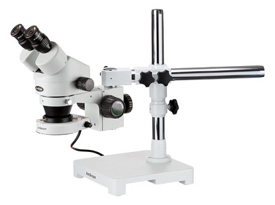
I have this AmScope microscope with a WD165 0.5X attachment lens.
I wanted one for years but couldn't afford it; they are very expensive! The model I wanted has a double arm boom which is more stable and prevents tilting. A model with a camera mount would have been ideal; it's very difficult to snap a photo from the eyepiece. I watched for local sales until this one popped up and I got it for a fraction of the price. It doesn't have all the features I would have liked but the microscope part is still there.
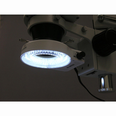
The zoom lens I mentioned is needed to be able to see as far down as a circuit board laying on a desk. And the LED attachment is absolutely necessary to see anything at all.
There is of course more skill involved in soldering and the quality of equipment matters but you will be amazed at how well you will still improve instantly just by being able to SEE what you're doing. What the microscope does it allow you to react to tiny movements that you just can't see with the naked eye even with perfect coordination. This lets allows you to perform very fine movements that would otherwise be imperceptible.
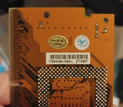
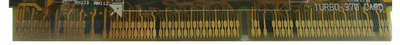
There are also faults that can be seen with a microscope but not with the naked eye such as a cracked solder join and loose pins on fine pitch flat packs.
61Kg1w2mPHL._SL1500_eb919d67-df63-4152-b8b8-e0ca66222765_2048x2048.jpg
61lZqOinUjL._SL1200_48568f80-ec6e-4415-96f1-efa84b38d72d_2048x2048.jpg


