VOGONS


Reply 40 of 50, by tony359

User metadata
Rank Member
Rank
Member

Another update.

I swapped the KBC chip 245: no change.
I checked the resistor packs we talked about, I found the one which is connected to the 8bit data lines. All seems to be ok. It's not on the last slot though? I measured 10KOhm between each leg and the common pin and 0.7KOhm between the common pin and ground. I can measure 1KOhm between the ISA pins and the common pin of the resistor pack.
I then found another 245 connected to the 8 bit data line and that was interfacing the CPU with the bus. I swapped that too but nothing. Would I be correct in thinking that this chip is basically responsible to generate the data lines I see on the ISA bus?

In fact, I now see DOOM crashes even more often if not mistaken. Either it fails to load or it freezes. I've noticed that when the keyboard fails, the graphic seems to stutter for a moment before either everything freezes or the keyboard "gets stuck".

I underclocked to 33Mhz: no change
I changed the WS to the highest possible values: no change
I changed the cache timing to the highest possible values: no change
I set the ISA bus to a lower speed: no change

One thing I noticed is that once the board crashes, I have to power cycle and keep it off for several seconds or the HDD controller would fail to start. Now, sometimes the HDD controller fails to start anyways 😀 I'm wondering if all this hassle is caused by a dodgy HDD controller. Maybe I should source another one, the other one I have is VLB. This one works on other motherboards though.

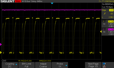
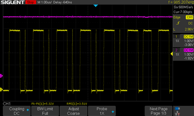
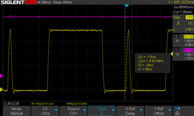
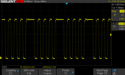
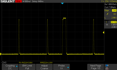
During all the above tests, the ISA bus still looks pretty poor.

Help! 😀

My Youtube channel: https://www.youtube.com/@tony359

Reply 41 of 50, by Deunan

User metadata
Rank Oldbie
Rank
Oldbie

Sometimes the chipset talks to the ISA directly, sometimes there's a '245 or two used as buffers. Usually there is a '245 for the on-board chips like KBC and RTC, just one is enough because that data bus is 8-bit. This one will not be present on mobos where both KBC and RTC are integrated into chipset already.

A weak ISA card can easily mess the system up, this is not PCI where everything sits behind a bridge, ISA has signals that can suspend CPU (usually for DMA, but not generating ready signal can have similar effect) and even interfere with RAM refresh. So yeah, do try another HDD controller.

Reply 42 of 50, by tony359

User metadata
Rank Member
Rank
Member

time to get a XT IDE card I guess! 😀 Two birds with one stone.

I'll check with no ISA controller first, if I see the same "weak" signals, then I am at a loss to be honest. I'll also check the signals coming from the CPU - even though they go through the 245 so it shouldn't matter.

My Youtube channel: https://www.youtube.com/@tony359

Reply 43 of 50, by weedeewee

User metadata
Rank l33t
Rank
l33t

some things that popped to mind...
Could this 'weak' signal be due to broken or missing decoupling caps ?
Is the voltage level the same/similar across the board?

for example, I once had a board that was crashing regularly. I though I had to recap the psu which I didn't really feel like.
The voltages all measured fine on the power connector itself, yet on the side of the mainboard further away from the mainboard the voltages dropped off.
Eventually figured out that the problem were the contacts of the power connector itself being slightly oxidized and causing a significant enough voltage drop when the machine was running.
As in 5v on the power connector and only 4.2V on the other side of the board.

Right to repair is fundamental. You own it, you're allowed to fix it.
How To Ask Questions The Smart Way
Do not ask Why !
https://www.vogonswiki.com/index.php/Serial_port

Reply 44 of 50, by Deunan

User metadata
Rank Oldbie
Rank
Oldbie
weedeewee wrote on 2022-02-24, 12:30:

Could this 'weak' signal be due to broken or missing decoupling caps ?

Yes, though the usual case (at least for me) is not a whole mobo brownout but a corroded trace or via on the power supply to one specific chip. This is both difficult to find and causes somewhat random instability. Only once I had to deal with a power connector that I did clean of obvious corrosion but clearly it was oxidized too much anyway - I had the voltage status LEDs on POST card dim or not even come up. I had to desolder and re-tin the contacts as I didn't want to waste a replacement part on what was already mostly a ressurection and not a proper repair.

BTW if replacing the '245 doesn't really help much with the signal shapes then maybe the culprit is the tristate or direction control line slopes being too slow. People tend to think of these signals as 0/1 but it's all analog inside. If the control signal lingers too long in the no-mans land between 0 and 1 states, the outputs will follow and not drive properly.

Reply 45 of 50, by tony359

User metadata
Rank Member
Rank
Member

More tests done.

Voltages are ok across the board. I connected channel 1 directly to the 5V from PSU and I was probing with channel B which was overlaid on channel 1. No difference. Voltage is 4.85 everywhere.

More tests:
1. The wonky BUS is present with no cards connected
2. The data line on the 80386 chip end (behind the 245) looks ok
3. When the keyboard stops working (nothing crashed this time) there is nothing visible on the VCC line (voltage drops etc)
4. If I remove the CPU-side 245 (no boards), the ISA Bus is still wonky (even though it only appears for a second - or doesn't do anything at all, it depends)
5. If I remove the KBC chip 245 (CPU 245 back in place and no boards), I get some weird signal - still wonky I presume

SDS00010.png
Filename
SDS00010.png
File size
30.06 KiB
Views
395 views
File license
Public domain

6. If I remove both 245 (no boards) I don't get anything
7. With the 245 back in place if I remove the KBC chip, the bus is still wonky
8. If I remove the BIOS, there is no activity on the bus
9. I peeled off the sticker of the BIOS and it's a MX27C512PC-15. I popped the chip in my TL866II and... it doesn't read. Fails pin check, ID check and even if I bypass everything it doesn't read anything. But it works on the board. I believe the 866II cannot program those chips but it should be able to read them?? I see the BIOS data pins go through a chip names KS83C206Q but I find no info online.
10. I scope'd the resistor pack connected to the bus. There are 5V on the common and I see the bus on each pin of the array. so all good here.
11. T/R and OE pins on the chips look ok, Deunan. Only, I see these spikes which are a bit suspicious as they seem to be too narrow for a bit? This is OE of the CPU-side 245.

SDS00011.png
Filename
SDS00011.png
File size
20.32 KiB
Views
395 views
File license
Public domain
SDS00012.png
Filename
SDS00012.png
File size
15.91 KiB
Views
395 views
File license
Public domain

TR pin on KBC chip (OE is tied to ground)

SDS00012.png
Filename
SDS00012.png
File size
15.91 KiB
Views
393 views
File license
Public domain

OE pin on CPU 245

SDS00013.png
Filename
SDS00013.png
File size
20.09 KiB
Views
393 views
File license
Public domain

I think it's enough for today 😀

Thanks for your support guys!

My Youtube channel: https://www.youtube.com/@tony359

Reply 47 of 50, by timigo

User metadata
Rank Newbie
Rank
Newbie

Hello, I have the same motherboard and the same problem with keyboard.
In my case the problem is in turbo switch function!
When I DISABLE the Turbo switch function motherboard works excellent and no problems with keyboard.

PS
My motherboard had broken traces around battery too, and keyboard did not work. I also fixed the traces.

Reply 48 of 50, by tony359

User metadata
Rank Member
Rank
Member

Thanks for that!

In my case it was the video card 😀 It was unstable and crashing everything. I tried with a different one and it's working fine! Took me AGES to realise!

My Youtube channel: https://www.youtube.com/@tony359

Reply 49 of 50, by kgiannis

User metadata
Rank Newbie
Rank
Newbie

Hello and thank you for describing all the process. I have seen your video in your YT channel (and also subscribed!)
I have the exact same board, bought as non-working because of battery leak and I am trying to fix it. So far:
- I have same rails damaged from corrosion, I fixed it though and I can verify continuity
- Next to the P8P9 header, there are 4 capacitors with 4μ7 value rate (4.7uF) which were all good, removed them and measured them. But in the end I replaced them with new ones.
- Just bellow these 4 capacitors, there was a ceramic one with indication "47" meaning 47pF. This one is destroyed and I have to replace it, waiting for the part to arrive BUT tbh I don't think this is critical and prevent the motherboard from posting
- There was a little corrosion on the 28pin socket for the BIOS so I replaced the socket with a new one.
- To this point, I don't see any other problem with traces and physically all looks good

The problem:
- The system is not posting at all 🙁
- I am using a POST card. I cannot see even the dashes on the POST card. Only the +12V LED is lit.
- I can measure +5V on the chips (controller and bios) even if the POST card is not showing activity for the +5V
- I am getting a continuous beep from the speaker which is not stopping, only when I turn off the switch.

Any ideas?
Is there anything I can measure (voltages?) that might help?
I am a hobbyist so I don't have a deep knowledge of electronics

Thank you in advance for any help

UPDATE:
- I forgot to mention that I measured the voltages on the 8bit ISA slot and I am getting correct voltages in pins (+5V, +12V, -12V), so maybe I have a bad POST card analyzer

Reply 50 of 50, by tony359

User metadata
Rank Member
Rank
Member

I'm sorry, I missed this message.

Silly question: do you have your post-card plugged the right way round? 😀 I made that mistake once!

If so, well then you might have a bad one indeed.

The continuous beep is weird. Have you got any further than your previous message?

My Youtube channel: https://www.youtube.com/@tony359