VOGONS


First post, by nathanieltolbert

User metadata
Rank Member
Rank
Member

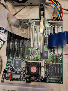
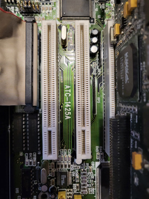
Hello everyone. I know I am posting again and I apologize if I am causing frustration or upset. I recently came across a 486 motherboard with PCI slot. The battery had been removed and it had a strange circle on the board which made me think it could have either a varta battery or a cr2032 holder. I went ahead and purchased it. I was slightly nervous because I haven't had great luck shipping internationally lately, but it arrived yesterday. It came with a CPU, 32MB of RAM and 256K of Cache. I checked the board visually as best as I could and everything appears to be okay. There doesn't even seem to be any damage under where the Varta Battery would have gone, although it is clear one was installed and removed. I looked at the board and it's labeled as an ATC-1425A. After some googling I was able to find a partial list of the Jumper settings on ELVHB website and some more information on the Win3x website as well. The board seems to be in decent shape and it safely arrived which makes me very happy. But I have a couple of curious questions.

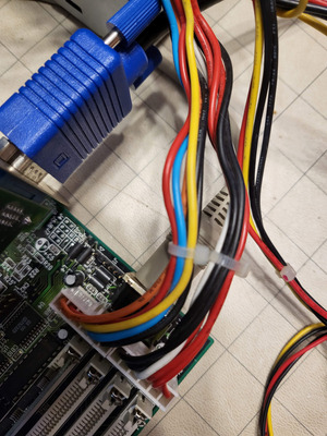
The first question is this - the partial jumpers page I found shows a jumper for setting to an external battery. Looking around the board I can see one single jumper labeled J1 which is keyed. Is this the external battery connector? It appears to have one pin more than the other external battery connectors I have encountered, but those are usually on a proprietary board from a big box manufacturer. Second, if there is an outline that appears to indicate that the board could be fitted at manufacturing with a CR2032 battery holder, is it possible for me to install one? Third, if I can install that battery holder, like in other boards, is there a spot where I will need to install a diode to block charging flow? And the last question I have is dealing with using the PCI for a video card. I have several different video cards that I am testing with. I was curious about two fairly low end (from what I understand) graphics cards, one is a Trident TGUI9680 with 1MB of RAM, the other low end card is a Cirrus Logic CL-GD5434 with 1MB of RAM as well. Frame rates seem to be pretty consistent in the Dosbenchmark suite from Phil's Computer Lab (Thank you again for making this suite. I would not even know where to grab a lot of these programs if this didn't exist) The Trident scores 53.0 in 3DBench 1.0, and the Cirrus card scored 54.9. Looking at these cards in Speedsys the Trident shows a video RAM speed of about 9.5MB/s and the Cirrus Logic card shows a video RAM speed of about 11 MB/s. I have a Matrox Mystique with 2MB in there now and the RAM speed on that is listed as 21.5 MB/s But in 3DBench it scores a 55.5. Do these speeds indicate that both of the 1MB cards aren't interleaving the RAM on the card? Or am I missing something?
Last question - I saw on the Win3x site that there is a driver for the IDE for DOS and Windows. Is this required? As it currently stands I'm getting about 3 MB/s on the IDE transfer speed. The drive is recognized by the BIOS and running in Mode 4. Is that PIO Mode 4? Should I be getting closer to 16 MB/s or is that just the theoretical max for PIO Mode 4.

If anyone knows where I can find a diagram that lets me know what the jumpers that aren't covered in the web page I found I would be very appreciative. If there is any additional information that is needed, please let me know. I will post a couple pictures here as soon as I can take them. Thank you.

Regards,

Nathan

Reply 1 of 24, by BitWrangler

User metadata
Rank l33t++
Rank
l33t++

It has been seen in the wild with CR2032 holder mounted, such as in the pic here... https://www.ultimateretro.net/en/motherboards/6675
The IDE drivers should enable 32bit DMA transfer modes which will speed disk access up a bit in windows, they may work well in DOS also, but beware of older software in DOS that hammers the BIOS routines or hardware directly and might screw up.

Last edited by Stiletto on 2021-11-11, 20:22. Edited 1 time in total.

Unicorn herding operations are proceeding, but all the totes of hens teeth and barrels of rocking horse poop give them plenty of hiding spots.

Reply 2 of 24, by nathanieltolbert

User metadata
Rank Member
Rank
Member

Okay. So if I was going to use Windows 95 then the IDE drivers would speed up drive access in Windows, otherwise the 3-4MB/s I am getting in DOS is as expected. I saw in that picture on the Win3X that they had a cr2032 battery holder installed, but I cannot see if there any additional diodes or parts added to block recharging the battery?

Reply 3 of 24, by nathanieltolbert

User metadata
Rank Member
Rank
Member

Here are the pictures of the motherboard.

This one is the motherboard overall -

20211109_140502.jpg
Filename
20211109_140502.jpg
File size
1.88 MiB
Views
1397 views
File license
Public domain

This one shows the model number that is listed on the motherboard -

20211109_140512.jpg
Filename
20211109_140512.jpg
File size
1.46 MiB
Views
1397 views
File license
Public domain

And finally this one shows the connector labeled J1 near the AT port on the board -

20211109_140520.jpg
Filename
20211109_140520.jpg
File size
877.25 KiB
Views
1397 views
File license
Public domain

When looking on the Win3x website there is no dump of the BIOS, is that something that would be wanted as well?

Reply 5 of 24, by BitWrangler

User metadata
Rank l33t++
Rank
l33t++

Seeing J1, I would make a guess, lacking further info, that the 5-6 pins nearest the keyboard connector will want a jumper for external battery enable and the pins 1-4 are where the external battery plugs in. But that's just based on seeing similar configs not this particular board.

Unicorn herding operations are proceeding, but all the totes of hens teeth and barrels of rocking horse poop give them plenty of hiding spots.

Reply 6 of 24, by nathanieltolbert

User metadata
Rank Member
Rank
Member

The jumper settings sheet I found indicated JP11 has 3 different settings. 1-2 indicates use of internal battery, 2-3 indicates use of external battery, and 2-3 resets CMOS. JP11 is in a different area towards the middle of the board. So, if that information is correct, I still have no clue what J1 is. It doesn't appear to be a jumper point because this board very much labels everything that is to have jumpers with JPxx. But as is normal with this sort of thing, I am more than likely wrong. If you all think I would be safe attaching a CR2032 battery holder to the board in the specific spot, then I can do that. I have 4 or five more of the coin holders from my prior project. Also thank you for the pointing me to Ultimateretro.net. I will be sure to bookmark it.

Reply 7 of 24, by BitWrangler

User metadata
Rank l33t++
Rank
l33t++

Oh, if there is an indicated battery jumper then J1 is next most likely to be a PS/2 header.

Unicorn herding operations are proceeding, but all the totes of hens teeth and barrels of rocking horse poop give them plenty of hiding spots.

Reply 8 of 24, by nathanieltolbert

User metadata
Rank Member
Rank
Member

Oh, so J1 could be a PS/2 Mouse header? That thought never even occurred to me. That still brings up the question of where I plug in the external battery then. Nothing particularly stands out to me as being a connector for an external battery even though it states that it can take one. It will probably have to stay a mystery to me for now. Thank you for the information so far. I really do appreciate it.

Reply 9 of 24, by turbooo

User metadata
Rank Newbie
Rank
Newbie

It should be J11 that controls the internal/external battery connection, not JP11, correct? It looks like it would be that 4 pin header closest to the battery connector. It would make more sense to be located there as well.

Reply 11 of 24, by nathanieltolbert

User metadata
Rank Member
Rank
Member
turbooo wrote on 2021-11-11, 18:46:

It should be J11 that controls the internal/external battery connection, not JP11, correct? It looks like it would be that 4 pin header closest to the battery connector. It would make more sense to be located there as well.

Oh, you're correct. It is labeled J11 and not JP11. The 4 pin header closest to the battery is J36. It appears to have a + and a - silkscreened on the board next to the connector. I do not know if that is for that pin header, but I see nothing else nearby. I don't see anything in the jumper settings table that I found that references j36 being used for anything. It won't kill the board, if I put an external 3V battery on there, will it?

Reply 12 of 24, by turbooo

User metadata
Rank Newbie
Rank
Newbie

I’d recommend against sticking random voltages on pins, probably won’t kill the board but might cause other issues.

If you have a multimeter you can check the resistance between the negative pin and a ground (should be 0 ohms) and the positive pin and either J11 pin 1 or pin 3, one of those two (should be pin 1 ideally) would be 0 ohms.

Reply 13 of 24, by nathanieltolbert

User metadata
Rank Member
Rank
Member
turbooo wrote on 2021-11-12, 21:06:

I’d recommend against sticking random voltages on pins, probably won’t kill the board but might cause other issues.

If you have a multimeter you can check the resistance between the negative pin and a ground (should be 0 ohms) and the positive pin and either J11 pin 1 or pin 3, one of those two (should be pin 1 ideally) would be 0 ohms.

I have a multimeter, but I have never been super proficient with it. I will definitely try it tomorrow, right now I'm scratching my head because I have an old asetec psu here with no fuse and the silkscreen value seems wrong. 250V T4AH which is a 4 Amp ceramic slow blow fuse. I thought all fuses on computer power supplies were fast blow? I have to clean it before I even think of replacing the fuse. It's full of dust and detritus. I will try your suggestion of checking if there is resistance between the pins. To confirm, I have to have a psu plugged in and running to test that, right?

Reply 14 of 24, by fool

User metadata
Rank Member
Rank
Member

To confirm, I have to have a psu plugged in and running to test that, right

Power supply needs to be turned OFF. As ground point I have used mounting screw holes or molex plug black wire.

Toshiba T8500 desktop
SAM/CS9233 Wavetable Synthesizer daughterboard
Coming: 40-pin 8MB SIMM kit, CS4232 ISA wavetable sound card

Reply 16 of 24, by nathanieltolbert

User metadata
Rank Member
Rank
Member

Okay! I have tested the pins with the power off. I think that the jumper information I found is not quite accurate. The listing for j11 shows that it is a 4 pin header. But the header for j11 on my board is only 3 pins. I checked all of the pins on j11 to the pins on j36 and did not get any sort of response. The multimeter just read 1. When checking the last pin on j36 and the ground plane it immediately dropped to 0.00 so there appears to be continuity there. But I don't know where the + pin goes to.

Reply 17 of 24, by turbooo

User metadata
Rank Newbie
Rank
Newbie

Hmm, okay that was my suspicion that there was something funny with the online jumper settings, they seem close but still off, as you’ve noted.

You can try this instead, check the resistance between pin 3 of J36 and the positive pin of the battery connector on the motherboard, that should read 0 ohms (remove the jumper for these measurements). Pin 2 and the same battery pin should read open circuit (i.e., 1), same for pin 1. If that is the case then you should be able to connect your external battery to pin 2 and a ground pin and I think that should do the trick.

Reply 18 of 24, by nathanieltolbert

User metadata
Rank Member
Rank
Member

Well, that was strange. I removed the jumper on j11 just in case, and then I tried as you suggested. I got nothing. It stayed on 1. I tried every other pin. Same result. Checked the negative side and the pin that has the negative symbol next to it on J36. Got a result there. So I took a picture of all of the jumper settings and removed all of the jumpers on the board. tried again. Nothing. No result on any pin. That shouldn't be possible, unless there's damage on the board, right? I guess I need to look really close on the board for trace damage.

Reply 19 of 24, by turbooo

User metadata
Rank Newbie
Rank
Newbie

It’s a little strange but let’s not panic just yet.

It seems the SIS 497 chip has an integrated RTC, so here’s one more thing to try: check whether any of the pins on J36 connect to pin 37 of the the 497 (you can see on the silkscreen that the right side of the bottom edge is pin 40 so work leftwards from there). Failing that, you can also check J11 and pin 37. Hopefully one of those will read 0 ohms.