ArcadEd wrote on 2021-12-12, 23:36:
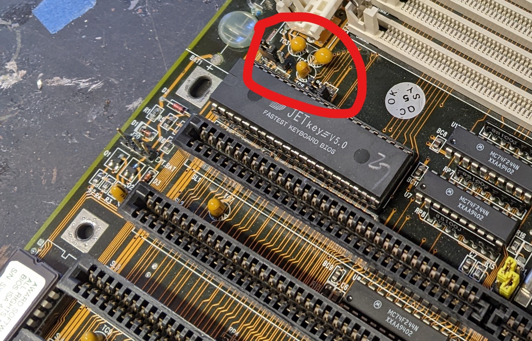
Thanks. I already pulled the connector because I wasn't sure if there was any damage under it. It looks like there might be a little button CAP (mustard colored, circled in picture). I feel like the 12v passes through one of those, but I'm not entirely sure. If it does, would it be ok to bypass it? I assume not, but I'm not entirely sure here. 😀
I'm glad you asked. Your basic ideas are kind-of correct, but your conclusion is plain wrong. The "little mustard colord button CAPs" are in fact capacitors. To be more precise, they are a special kind of electrolytic caps called "tantalum caps", which can be seen as predecessor of modern low-ESR electrolytic caps. Your picture has three caps there, and it is very likely that the three caps are for the three "ISA-only" voltages +12V, -12V and -5V. There are enough caps on +5V distributed around the whole board, but there is only a single cap on each of those three voltages, and those are the caps you show. As the voltage comes from the power supply connector and only connects to the ISA slots (on some mainboards, +12V is used for some fringe purpose), this position between the AT power connector and the ISA slots is the ideal position to place these capacitors. So you are exactly right that one of them is related to +12V.
But you are wrong in assuming that +12V passes through the capacitor. It's exactly the opposite. Capacitors don't pass DC voltages. Capacitors help to stabilize DC voltages. One end of the capacitor is connected to the DC voltage you want to "stabilize", and the other end of the capacitor is connected to a "stable reference point". In case of most electronics, the stable reference point is called "ground", which is the level of the black wires in the Molex connectors and the level of the case. You do not want to "bypass" the capacitor (i.e. connect both legs using some wire). This would create a short circuit between +12V and ground, which is a really bad idea. In fact, tantalum caps from the early 80s are known to fail creating a short circuit, especially if they were unused for a long time. Many people trying to re-start their XT computers found one or more of these capacitor shorting out a supply voltage, getting overly hot, catching fire (just the cap, no big flames), and emitting some fume and bad smell. Usually no permanent damage is created by tantalum caps breaking down.
On an AT board, the +12V pin of the AT power connector is supposed to directly connect to the ISA slot, usually through a wide trace (like 0.1" / 2.5mm). It does not "go through" any components, although it is usually touches some components, especially the tantalum cap you identified. If you don't get +12V at the ISA slots, either your ATX/AT converter is broken and not forwarding the +12V to the board, or the trace on the board has been eaten away by battery leakage. You can easily use a continuity tester to test (with the computer powered off!) from the +12V on the molex connector to the +12V pin on the back of the board at the AT power connector. If you get a beep, your ATX/AT adapter is fine. You can continue to use the continuity tester to test the connection on the the board, from the power supply connector to the ISA slots. If there is no connection, the trace is interrupt. As a trace is just an electical connection, a wire to bridge over the "hole" in the trace is enough to fix the issue.