VOGONS


Asus P2B Motherboard: No support for PIII?

Topic actions

Reply 40 of 74, by biessea

User metadata
Rank Member
Rank
Member
teclillass wrote on 2021-12-16, 16:32:
Q: How do I find out which voltage regulator chip I have and what voltages it can provide? A: You need to look at the board. Nea […]
Show full quote

Q: How do I find out which voltage regulator chip I have and what voltages it can provide?
A: You need to look at the board. Near the Slot1 connector there is a chip with around 30 pins or so. Some of these chips can provide 1.3V-3.5V, while others can only provide 1.8V-3.5V. Attention, dual-cpu boards have two voltage regulator chips, and it is possible that one is of the new type and the other not!
Chips that can provide voltages down to 1.3V:
HIP6019BCB
HIP6020ACB
HIP6004CB
HIP6004BCB
US3007CW

Chips that can only provide voltages down to 1.8V:
HIP6019CB
HIP6004ACB

This list is not complete. Asus has used quite a lot of different voltage regulator chips on its boards, so it's possible there are even more that Asus used I'm not aware of.

web:
https://web.archive.org/web/20191114013933/ht … pgrade_faq.html

vogons:
Asus P2B rev. 1.04

Oh guy, it's incredible.

I have two SLot1 motherboard working, one repaired by me (Asus P2B rev.1.02) and one Chaintech 6BPM0.

These motherboard has these two voltage regulator that doesn't provide 1,3v. but the 1.8v. minimum.

The Asus has the HIP6019cb chip.

The Chaintech has the HIP6004ACB.

So I have no possibility to upgrade boards with two Coppermine 700mhz that I found near my home?

Computer lover since 1992.
Love retro-computing, retro-gaming, high-end systems and all about computer-tech.
Love beer, too.
Reply 41 of 74, by Paadam

User metadata
Rank Member
Rank
Member

Please read again this thread 😀 With Coppermine Slot1 you can mask VID pins so that the board delivers 1.8v which is perfectly normal for Coppermines. With 370+slot1 adapter you can usually just use voltage selection jumpers and set it to 1.8v and done, it works.
Also, you can replace HIP6004ACB with HIP6004BCB and it supports every voltage.
If you are not able to do the aforementioned things then sorry no, you cannot use Coppermine on your board.

Many 3Dfx and Pentium III-S stuff.
My amibay FS thread: www.amibay.com/showthread.php?88030-Man ... -370-dual)

Reply 42 of 74, by biessea

User metadata
Rank Member
Rank
Member
Paadam wrote on 2023-01-23, 18:19:

Please read again this thread 😀 With Coppermine Slot1 you can mask VID pins so that the board delivers 1.8v which is perfectly normal for Coppermines. With 370+slot1 adapter you can usually just use voltage selection jumpers and set it to 1.8v and done, it works.
Also, you can replace HIP6004ACB with HIP6004BCB and it supports every voltage.
If you are not able to do the aforementioned things then sorry no, you cannot use Coppermine on your board.

Thanks, I didn't read all the thread cause I read a lot everywhere.

I can't replace the voltage regulator, but if I update the bios at the 1012 version and I mask the pin I will be ok? Now I read better the thread trying to understand.

Computer lover since 1992.
Love retro-computing, retro-gaming, high-end systems and all about computer-tech.
Love beer, too.
Reply 43 of 74, by biessea

User metadata
Rank Member
Rank
Member

Ok, I read it all.

Nice.

I have a old revision 1.02 with the three pins for selecting FSB speed (and in the manual is written that I can choose 133fsb).

Now,in first instance I will have to update the bios to the 1012 version (I don't want to put beta bios on it).
Then which pin I have to cover of the coppermine slot 1 processor?

I think 1,8v. is perfectly ok for the coppermine to be overclocked too 😉

Computer lover since 1992.
Love retro-computing, retro-gaming, high-end systems and all about computer-tech.
Love beer, too.
Reply 44 of 74, by biessea

User metadata
Rank Member
Rank
Member
Paadam wrote on 2023-01-23, 18:19:

Please read again this thread 😀 With Coppermine Slot1 you can mask VID pins so that the board delivers 1.8v which is perfectly normal for Coppermines. With 370+slot1 adapter you can usually just use voltage selection jumpers and set it to 1.8v and done, it works.
Also, you can replace HIP6004ACB with HIP6004BCB and it supports every voltage.
If you are not able to do the aforementioned things then sorry no, you cannot use Coppermine on your board.

Please, can you tell me the pin mod that I have to do in a Pentium 3 Coppermine Slot1 factor? Which pin I have to mask to make bootable and working with my Asus p2b 1.02?

Computer lover since 1992.
Love retro-computing, retro-gaming, high-end systems and all about computer-tech.
Love beer, too.

Reply 45 of 74, by Paadam

User metadata
Rank Member
Rank
Member

https://www.motherboardpoint.com/threads/piii … in-a-p2v.15438/

Many 3Dfx and Pentium III-S stuff.
My amibay FS thread: www.amibay.com/showthread.php?88030-Man ... -370-dual)

Reply 46 of 74, by biessea

User metadata
Rank Member
Rank
Member
Paadam wrote on 2023-01-24, 10:46:

I am reading this forum various times, and I am not sure I have understand very well. It seems an hard work to do Anyway.

Can you explain with your words what I have to do to "modify" Coppermine processor to "ask" to the motherboard 1,8v. Instead of standard 1.65?

I make difficult to understand unfortunately, I need more help please.

Computer lover since 1992.
Love retro-computing, retro-gaming, high-end systems and all about computer-tech.
Love beer, too.

Reply 47 of 74, by BitWrangler

User metadata
Rank l33t++
Rank
l33t++

Look for references to VID pin taping or masking

Unicorn herding operations are proceeding, but all the totes of hens teeth and barrels of rocking horse poop give them plenty of hiding spots.

Reply 48 of 74, by biessea

User metadata
Rank Member
Rank
Member
BitWrangler wrote on 2023-01-25, 18:45:

Look for references to VID pin taping or masking

I'm not sure I had understood the logic behind that operation but anyway, I did understand that I have to mask or insulate two little pin and give another one a direct contact.

The problem is that I don't knwo how to do these operations. There is some photo of a Coppermine modified somewhere?

Computer lover since 1992.
Love retro-computing, retro-gaming, high-end systems and all about computer-tech.
Love beer, too.

Reply 49 of 74, by BitWrangler

User metadata
Rank l33t++
Rank
l33t++

Dude where's my voltage regs?

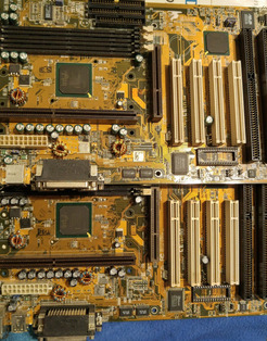
Turned up two P2Bs today a 1.01 and a 1.10, I received them in a scrap lot ~15 years ago though and they had been robbed out prior. I have more P2bness to find though, these might donate a part or two.

Attachments

  • sadp2b.jpg
    Filename
    sadp2b.jpg
    File size
    1 MiB
    Views
    1074 views
    File comment
    Formerlly scrapped P2bs.
    File license
    Public domain

Unicorn herding operations are proceeding, but all the totes of hens teeth and barrels of rocking horse poop give them plenty of hiding spots.

Reply 50 of 74, by biessea

User metadata
Rank Member
Rank
Member
BitWrangler wrote on 2023-01-28, 02:02:

Dude where's my voltage regs?

Turned up two P2Bs today a 1.01 and a 1.10, I received them in a scrap lot ~15 years ago though and they had been robbed out prior. I have more P2bness to find though, these might donate a part or two.

Omg voltage regulator and some mosfet gone here...

Computer lover since 1992.
Love retro-computing, retro-gaming, high-end systems and all about computer-tech.
Love beer, too.

Reply 51 of 74, by biessea

User metadata
Rank Member
Rank
Member

So please, no photo about coppermine modified to run in an Asus p2b 1.02 with voltage regulator not compatibile?

I'm not sure, but I have to modify the cpu right?

Directly on the contact pins or inside the cartridge of the processor?

I'm still confused and I need help, please.

Computer lover since 1992.
Love retro-computing, retro-gaming, high-end systems and all about computer-tech.
Love beer, too.

Reply 52 of 74, by PARKE

User metadata
Rank Oldbie
Rank
Oldbie
biessea wrote on 2023-01-28, 14:02:
So please, no photo about coppermine modified to run in an Asus p2b 1.02 with voltage regulator not compatibile? I'm not sure, b […]
Show full quote

So please, no photo about coppermine modified to run in an Asus p2b 1.02 with voltage regulator not compatibile?
I'm not sure, but I have to modify the cpu right?
Directly on the contact pins or inside the cartridge of the processor?
I'm still confused and I need help, please.

The simplest way to do it is plugging a piece of wire in the slot on the motherboard and is described here:
http://tipperlinne.com/p2b-ds.htm
scroll down to:

Slot 1 Processor VID Pins

Slot 1 Connector VID Pins

U-Shaped Wire

Reply 53 of 74, by biessea

User metadata
Rank Member
Rank
Member
PARKE wrote on 2023-01-28, 15:01:
The simplest way to do it is plugging a piece of wire in the slot on the motherboard and is described here: http://tipperlinne.c […]
Show full quote
biessea wrote on 2023-01-28, 14:02:
So please, no photo about coppermine modified to run in an Asus p2b 1.02 with voltage regulator not compatibile? I'm not sure, b […]
Show full quote

So please, no photo about coppermine modified to run in an Asus p2b 1.02 with voltage regulator not compatibile?
I'm not sure, but I have to modify the cpu right?
Directly on the contact pins or inside the cartridge of the processor?
I'm still confused and I need help, please.

The simplest way to do it is plugging a piece of wire in the slot on the motherboard and is described here:
http://tipperlinne.com/p2b-ds.htm
scroll down to:

Slot 1 Processor VID Pins

Slot 1 Connector VID Pins

U-Shaped Wire

Yes thanks, directly a U wire on the socket, to make continuity putting ground one pin yes.

But in this example they start from a 1.7 processors.

I have 1.65 processors Coppermine, this will change a lot I'm thinking to have 1.8v. isn't it?

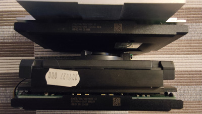
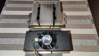
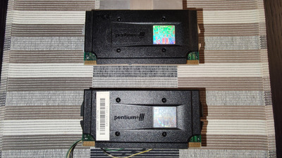
PS: I attach the images shown two coppermines processors that I have just bought today to put in the Asus P2B 1.02. Which one deserve better to be there? The 100fsb one?

Attachments

  • pentium 3 coppermines.jpg
    Filename
    pentium 3 coppermines.jpg
    File size
    509.11 KiB
    Views
    1033 views
    File comment
    Pentium 3 coppermines 3
    File license
    Public domain
  • pentium 3 coppermines 3.jpg
    Filename
    pentium 3 coppermines 3.jpg
    File size
    964.27 KiB
    Views
    1033 views
    File comment
    Pentium3 coppermines 2
    File license
    Public domain
  • pentium 3 coppermines 2.jpg
    Filename
    pentium 3 coppermines 2.jpg
    File size
    971.56 KiB
    Views
    1033 views
    File comment
    Pentium 3 coppermines
    File license
    Public domain

Computer lover since 1992.
Love retro-computing, retro-gaming, high-end systems and all about computer-tech.
Love beer, too.

Reply 54 of 74, by biessea

User metadata
Rank Member
Rank
Member

If you look carefully this magnified images taken just from my Coppermine 1.65v. you can see that I will have more work to do.

Cause 1,65v. is :

Voltage VID4 VID3 VID2 VID1 VID0
1.65V 0 1 0 0 0
1.80V 0 0 1 0 1 <--- You want these values

So If I am not mistaken I have to change the VID3 state, the VID2 state and VID0 state.

Two of them I have to "cut them" so the voltage regulator doens't see nothing, and the one I have to ground (using that famous U wire on the slot 1). It's correct?

So I have to modify these two VID2 and VID0 cutting the traces on the CPU, is this correct?

Sorry but I ask a lot cause I am in a confusion and I want to make permanent damage on the CPUs...

Computer lover since 1992.
Love retro-computing, retro-gaming, high-end systems and all about computer-tech.
Love beer, too.

Reply 55 of 74, by PARKE

User metadata
Rank Oldbie
Rank
Oldbie
biessea wrote on 2023-01-28, 16:15:

Yes thanks, directly a U wire on the socket, to make continuity putting ground one pin yes.
But in this example they start from a 1.7 processors.
I have 1.65 processors Coppermine, this will change a lot I'm thinking to have 1.8v. isn't it?

No.
The text reads:
ooooooooooooooooooooooooooooooooooooooooooooooooooo
If we can change VID1 from a '1' (open circuit) to a '0', (short circuit to ground), the processor will appear to be requesting 1.8v.
ooooooooooooooooooooooooooooooooooooooooooooooooooo
The keyword is 'will appear'.
This mod is done >on the motherboard< and it does not matter what type of cpu you stick into it because the motherboard will still signal that it needs 1.8volt.

Reply 56 of 74, by biessea

User metadata
Rank Member
Rank
Member
PARKE wrote on 2023-01-28, 16:58:
No. The text reads: ooooooooooooooooooooooooooooooooooooooooooooooooooo If we can change VID1 from a '1' (open circuit) to a '0 […]
Show full quote
biessea wrote on 2023-01-28, 16:15:

Yes thanks, directly a U wire on the socket, to make continuity putting ground one pin yes.
But in this example they start from a 1.7 processors.
I have 1.65 processors Coppermine, this will change a lot I'm thinking to have 1.8v. isn't it?

No.
The text reads:
ooooooooooooooooooooooooooooooooooooooooooooooooooo
If we can change VID1 from a '1' (open circuit) to a '0', (short circuit to ground), the processor will appear to be requesting 1.8v.
ooooooooooooooooooooooooooooooooooooooooooooooooooo
The keyword is 'will appear'.
This mod is done >on the motherboard< and it does not matter what type of cpu you stick into it because the motherboard will still signal that it needs 1.8volt.

Oh wow.

I didn't understood that.

On the motherboard??

So I can put every cpu that the motherboard will provide everytime 1.8volts??

It's enough to put the U wire so?

Now, the way the VID signals work, is the voltage regulator has
pullup resistors built in. If nothing is connected to the VID pin
on the voltage regulator, a logic "1" results. If the VID pin is
grounded, a logic "0" results.

The VID driving circuit on processors has varied a bit over the
years, and the latest processors _may_ have a full driver in
them. Older processors drive to ground or are open circuit on
the VID pins. (Pumping more than 5 milliamps into one of these
grounds, will damage it, so that is why just connecting the pin
to VCC won't work without the potential for collateral damage.)

What this means is, if your vintage of processor makes a logic "1"
on a specific VID signal (an open circuit), you can make it into a
zero, safely, by grounding the signal. This can be done, for example,
with a U shaped bridge inserted in the holes next to the Slot 1 socket.
Now, the example on this web page, is modifying VID1, and you need to
modify VID3 from a "1" to a "0". This means finding a GND on the
connector, near to B119. (The 244452 datasheet mentioned below, shows
there are no GND signals on the B side of the connector, so a longer
wire to reach the A side would be needed.)

http://tipperlinne.com/p2b-ds.htm

VID4 (Pin A121)
VID3 (Pin B119)
VID2 (Pin A119)
VID1 (Pin A120)
VID0 (Pin B120)

The hardest part, will be opening the circuit on VID2 and VID0. What
I did on my slocket, is cut the wire leading away from the gold pins
on the edge connector, as this breaks the GND signal coming from the
processor, to VID2 and VID0 on the motherboard. I use a hobby knife
(Xacto), and cut a 1mm section out of the track with two cuts. This
leaves a visible gap, suitable for verifying the connection is cleanly
cut. I make the cut far enough away from the edge card contact, that
I can solder a bridge wire in the future, if it is ever necessary
to return the module to "factory" condition.

If you read carefully this part in the site you mentioned to me, I can understand that I have to "cut" on slot1 two vid...

Computer lover since 1992.
Love retro-computing, retro-gaming, high-end systems and all about computer-tech.
Love beer, too.

Reply 57 of 74, by biessea

User metadata
Rank Member
Rank
Member
PARKE wrote on 2023-01-28, 16:58:
No. The text reads: ooooooooooooooooooooooooooooooooooooooooooooooooooo If we can change VID1 from a '1' (open circuit) to a '0 […]
Show full quote
biessea wrote on 2023-01-28, 16:15:

Yes thanks, directly a U wire on the socket, to make continuity putting ground one pin yes.
But in this example they start from a 1.7 processors.
I have 1.65 processors Coppermine, this will change a lot I'm thinking to have 1.8v. isn't it?

No.
The text reads:
ooooooooooooooooooooooooooooooooooooooooooooooooooo
If we can change VID1 from a '1' (open circuit) to a '0', (short circuit to ground), the processor will appear to be requesting 1.8v.
ooooooooooooooooooooooooooooooooooooooooooooooooooo
The keyword is 'will appear'.
This mod is done >on the motherboard< and it does not matter what type of cpu you stick into it because the motherboard will still signal that it needs 1.8volt.

I am sorry, but more than I read the link you copied to me and more I think you are wrong.

The processor tell the motherboard which voltage do it need.
So it's different if I have on my hand a 1.7v. (like the example on one page) or a 1.65v (like the example in the other page).
Modification will be different, this is quite clear.

Coppermine that I have are 1.65v. So

Voltage VID4 VID3 VID2 VID1 VID0
1.65V 0 1 0 0 0

If I put that U wire on the slot1 like you are trying to tell me I just have te results of

0 1 0 1 1 that is a non result cause in the table voltage this means to nothing.

Voltage VID4 VID3 VID2 VID1 VID0
A121 B119 A119 A120 B120
1.80 0 0 1 0 1
1.85 0 0 1 0 0
1.90 0 0 0 1 1
1.95 0 0 0 1 0
2.00 0 0 0 0 1
2.05 0 0 0 0 0
No Core 1 1 1 1 1
2.10 1 1 1 1 0
2.20 1 1 1 0 1
2.30 1 1 1 0 0
2.40 1 1 0 1 1

In the other link they explain how to work from a 1.65v. Coppermine to a 1.8v. State, but if you read carefully it's an hard work and I am not understanding very well what to do.

So please some other advice, can I try this mod to work?

Please I need this coppermine in my Asus p2b!

Last edited by biessea on 2023-03-14, 13:30. Edited 1 time in total.

Computer lover since 1992.
Love retro-computing, retro-gaming, high-end systems and all about computer-tech.
Love beer, too.

Reply 58 of 74, by Paadam

User metadata
Rank Member
Rank
Member

Just mask the needed pins with tape, no need to cut traces.

Many 3Dfx and Pentium III-S stuff.
My amibay FS thread: www.amibay.com/showthread.php?88030-Man ... -370-dual)

Reply 59 of 74, by biessea

User metadata
Rank Member
Rank
Member
Paadam wrote on 2023-01-28, 19:22:

Just mask the needed pins with tape, no need to cut traces.

Ok I will mask them with tape.

But you have understood that a pin VID 3 has to be grounded and how can I do it?

Vid3 is pin b119 on the slot 1 and in that side of the slot I have no other ground.

I will need a wire that go from the ground in A side of the slot1 to the b119 pin. How the hell can I put a wire and make it fixed in that position?

This seems to me absolutely hard, have you any idea?

Insulate other 2 pins will not be so hard I think.

Computer lover since 1992.
Love retro-computing, retro-gaming, high-end systems and all about computer-tech.
Love beer, too.