VOGONS


Asus P2B Motherboard: No support for PIII?

Topic actions

Reply 60 of 74, by rasz_pl

User metadata
Rank l33t
Rank
l33t
biessea wrote on 2023-01-28, 16:15:

I have 1.65 processors Coppermine, this will change a lot I'm thinking to have 1.8v. isn't it?

PS: I attach the images shown two coppermines processors that I have just bought today to put in the Asus P2B 1.02.

make sure your P2B only supports VRM8.1 specification (1.8-2.8v https://cdn.preterhuman.net/texts/computing/i … 0Guidelines.PDF) by reading model number of U1. Something like HIP6019, US3007, etc. VRM 8.2 spec already supported all the way down to 1.3V

Open Source AT&T Globalyst/NCR/FIC 486-GAC-2 proprietary Cache Module reproduction

Reply 61 of 74, by biessea

User metadata
Rank Member
Rank
Member

Q: Is it somehow possible to run slot1 cpus in boards which can only provide down to 1.8V?
A: Yes it's possible, but it requires some work. The basic idea behind the modification is the same as if you would be using a slotket adapter and use the voltage selection jumpers to make the board believe the cpu wants a different voltage.
There are 5 voltage identification signals (called VID0 - VID4), which must be altered (you don't need to touch VID4). To do this, you must tape some pins on the slot1 connector, and connect some others. It depends on the default voltage of your cpu which pins you'll have to modify, there are 3 possibilities. In all cases, you need to change the VID coding to 1.8V, i.e. (VID0 to VID3, from left to right) 1 0 1 0. A "0" means the signal is connected to ground, a "1" means it is open.
1.7V cpus: The cpu VID coding is (VID0 - VID3): 1 1 1 0. Only VID1 is different from the target 1.8V VID encoding, so you have to alter only VID1 to a logical 0. To do this, you need to connect VID1 to ground. VID1 is pin A120 on the connector, connect this to the adjacent A121 pin using a thin u-shaped wire piece.
1.65V cpus: cpu VID coding is (VID0 - VID3) : 0 0 0 1, so both VID0 (pin B120) and VID2 (pin A119) must be changed from a logical 0 to a logical 1. This can be done by insulating them, so just tape them. Additionally, VID3 (pin B119) must be changed to 0, thus needs to be connected to ground. Unfortunately, there is no adjacent ground pin, so use an insulated wire to connect it to A121 (just "around the corner" of the edge connector).

This another explaination make the things clear. Reading and reading I have understood that with mine 1.65v processors I need to insulate two pins ON THE PROCESSOR and wire two pin ON THE SLOT 1 SOCKET.

Computer lover since 1992.
Love retro-computing, retro-gaming, high-end systems and all about computer-tech.
Love beer, too.

Reply 62 of 74, by biessea

User metadata
Rank Member
Rank
Member
rasz_pl wrote on 2023-01-28, 20:15:
biessea wrote on 2023-01-28, 16:15:

I have 1.65 processors Coppermine, this will change a lot I'm thinking to have 1.8v. isn't it?

PS: I attach the images shown two coppermines processors that I have just bought today to put in the Asus P2B 1.02.

make sure your P2B only supports VRM8.1 specification (1.8-2.8v https://cdn.preterhuman.net/texts/computing/i … 0Guidelines.PDF) by reading model number of U1. Something like HIP6019, US3007, etc. VRM 8.2 spec already supported all the way down to 1.3V

I had written before that I have the old voltage regulator, I have to mod the cpu and the motherboard with a wire.

Computer lover since 1992.
Love retro-computing, retro-gaming, high-end systems and all about computer-tech.
Love beer, too.

Reply 63 of 74, by rasz_pl

User metadata
Rank l33t
Rank
l33t
biessea wrote on 2023-01-28, 20:18:
rasz_pl wrote on 2023-01-28, 20:15:
biessea wrote on 2023-01-28, 16:15:

I have 1.65 processors Coppermine, this will change a lot I'm thinking to have 1.8v. isn't it?

PS: I attach the images shown two coppermines processors that I have just bought today to put in the Asus P2B 1.02.

make sure your P2B only supports VRM8.1 specification (1.8-2.8v https://cdn.preterhuman.net/texts/computing/i … 0Guidelines.PDF) by reading model number of U1. Something like HIP6019, US3007, etc. VRM 8.2 spec already supported all the way down to 1.3V

I had written before that I have the old voltage regulator, I have to mod the cpu and the motherboard with a wire.

biessea wrote on 2023-01-23, 17:50:
teclillass wrote on 2021-12-16, 16:32:

The Asus has the HIP6019cb chip.

sorry I didnt scroll far back enough 🙁

Open Source AT&T Globalyst/NCR/FIC 486-GAC-2 proprietary Cache Module reproduction

Reply 64 of 74, by biessea

User metadata
Rank Member
Rank
Member
rasz_pl wrote on 2023-01-28, 20:25:
biessea wrote on 2023-01-28, 20:18:
rasz_pl wrote on 2023-01-28, 20:15:

make sure your P2B only supports VRM8.1 specification (1.8-2.8v https://cdn.preterhuman.net/texts/computing/i … 0Guidelines.PDF) by reading model number of U1. Something like HIP6019, US3007, etc. VRM 8.2 spec already supported all the way down to 1.3V

I had written before that I have the old voltage regulator, I have to mod the cpu and the motherboard with a wire.

biessea wrote on 2023-01-23, 17:50:
teclillass wrote on 2021-12-16, 16:32:

The Asus has the HIP6019cb chip.

sorry I didnt scroll far back enough 🙁

No problem mate,

At the end, correct me if I wrong.

With mine Coppermine 1,65v. Processor I will have to:

* update bios of my Asus p2b 1.02 to last official 1012 (or I need the last beta 1013?).

* connect VID3 (b119 pin on socket slot1) to GND (a121 pin on socket slot1 that is grounded)

* insulate VID 2 (a119 pin on processor) and VID0 (b120 pin on processor)

Then put the cpu on slot1 and motherboard will give 1,80v. and all should work.

Hope I can finally have understood all.

Computer lover since 1992.
Love retro-computing, retro-gaming, high-end systems and all about computer-tech.
Love beer, too.

Reply 65 of 74, by Paadam

User metadata
Rank Member
Rank
Member

Just solder small wire (a strand from IDE 80pin cable) to ground. There are plenty of grounds around, just measure with multimeter to verify.
These tasks are sort of obvious, if you are not able to perform basic modifications like masking/soldering etc then perhaps you should not do this. Or find someone locally who can.

Many 3Dfx and Pentium III-S stuff.
My amibay FS thread: www.amibay.com/showthread.php?88030-Man ... -370-dual)

Reply 66 of 74, by biessea

User metadata
Rank Member
Rank
Member
Paadam wrote on 2023-01-29, 06:34:

Just solder small wire (a strand from IDE 80pin cable) to ground. There are plenty of grounds around, just measure with multimeter to verify.
These tasks are sort of obvious, if you are not able to perform basic modifications like masking/soldering etc then perhaps you should not do this. Or find someone locally who can.

Yeah, no problem with soldering.

I just repaired the Asus P2B 1.02 that I want to give this Coppermine by finding the fault and re-soldering a Mosfet, the Q10.

Masking a pin isn't so difficult too I think, simply cutting a little piece of adesive tape and put on the correct pin.

A mod not so difficult, I think the problem was understanding really how to do.

Computer lover since 1992.
Love retro-computing, retro-gaming, high-end systems and all about computer-tech.
Love beer, too.

Reply 67 of 74, by PARKE

User metadata
Rank Oldbie
Rank
Oldbie
biessea wrote on 2023-01-28, 18:58:
I am sorry, but more than I read the link you copied to me and more I think you are wrong. The processor tell the motherboard wh […]
Show full quote

I am sorry, but more than I read the link you copied to me and more I think you are wrong.
The processor tell the motherboard which voltage do it need.
So it's different if I have on my hand a 1.7v. (like the example on one page) or a 1.65v (like the example in the other page).
Modification will be different, this is quite clear.
Coppermine that I have are 1.65v. So
Voltage VID4 VID3 VID2 VID1 VID0
1.65V 0 1 0 0 0
8><CUT

Yeah, I was cutting corners. ... sorry about that.
The mod with your 1.65v CPU plus only the U-shaped wire will produce 2.05volt.

Reply 68 of 74, by biessea

User metadata
Rank Member
Rank
Member
PARKE wrote on 2023-01-29, 12:33:
biessea wrote on 2023-01-28, 18:58:
I am sorry, but more than I read the link you copied to me and more I think you are wrong. The processor tell the motherboard wh […]
Show full quote

I am sorry, but more than I read the link you copied to me and more I think you are wrong.
The processor tell the motherboard which voltage do it need.
So it's different if I have on my hand a 1.7v. (like the example on one page) or a 1.65v (like the example in the other page).
Modification will be different, this is quite clear.
Coppermine that I have are 1.65v. So
Voltage VID4 VID3 VID2 VID1 VID0
1.65V 0 1 0 0 0
8><CUT

Yeah, I was cutting corners. ... sorry about that.
The mod with your 1.65v CPU plus only the U-shaped wire will produce 2.05volt.

Yes, and probably fry the CPU 😁

Anyway I read lot of times and I am happy to have understood better, now I know what to do.

Just I have spare time I will try that great mod.

Computer lover since 1992.
Love retro-computing, retro-gaming, high-end systems and all about computer-tech.
Love beer, too.

Reply 69 of 74, by biessea

User metadata
Rank Member
Rank
Member

Here I am finally!

I finally made the mod, not so easy but it worth a lot!! I have succeded in the mod and the motherboard give 1.8v. to the Coppermines and they run flawlessy!!!

I have one at 100mhz fsb another one at 133mhz fsb.

The first one is a 700mhz coppermine and it boots at 933mhz only sometimes. I put the photo anyway, probably I have to raise a little bit the voltage, 1.8 for that processor isn't enough to boot at 933mhz.

See photos mate!!!

I am so happy!

Now I can build my Windows 98SE slot1 system, overkill!

Attachments

  • 1677873784921.jpg
    Filename
    1677873784921.jpg
    File size
    651.8 KiB
    Views
    620 views
    File comment
    bios thermals
    File license
    Public domain
  • 1677869591719.jpg
    Filename
    1677869591719.jpg
    File size
    794.1 KiB
    Views
    620 views
    File comment
    the day I updated the bios with 1014.003 beta
    File license
    Public domain
  • 1677869591468.jpg
    Filename
    1677869591468.jpg
    File size
    403.01 KiB
    Views
    620 views
    File comment
    the ground on pin B119
    File license
    Public domain
  • 1677871898499.jpg
    Filename
    1677871898499.jpg
    File size
    462.74 KiB
    Views
    620 views
    File comment
    boot correct at 933mhz!
    File license
    Public domain
  • 1677869591448.jpg
    Filename
    1677869591448.jpg
    File size
    659.35 KiB
    Views
    620 views
    File comment
    testing the Vcore
    File license
    Public domain

Computer lover since 1992.
Love retro-computing, retro-gaming, high-end systems and all about computer-tech.
Love beer, too.

Reply 70 of 74, by biessea

User metadata
Rank Member
Rank
Member

Some boots even doesn't start with this Pentium 3 700mhz using 133fsb at 933mhz.

So i decided to see the table of the voltages and... luckily I see that raise the voltage to 1,85v. is even easiser to do, It ask this formula VID0 VID1 VID2 VID3: 0 0 1 0

Originally the 1.65 vcore processor has 0 0 0 1, so leaving the B119 pin to the ground I have to insulate only the A119 Pin (Vid 2).

I remove the insulation from the b120 pin and here we go!!!

We have 1,85v.

Now system seems to boot everytime, but I will let you know!

PS: I am so happy!

Attachments

  • 1677874699023.jpg
    Filename
    1677874699023.jpg
    File size
    798.37 KiB
    Views
    618 views
    File comment
    raising the vcore to 1,85v!
    File license
    Public domain

Computer lover since 1992.
Love retro-computing, retro-gaming, high-end systems and all about computer-tech.
Love beer, too.

Reply 71 of 74, by biessea

User metadata
Rank Member
Rank
Member

So after some test and playing games, I always had crashes randomly.

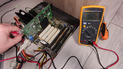
I decided to insulate other pins to give more voltage, but the situation doesn't get better until 1,95v.

In Prime95 the torture test failed after about one minute. It gives me always the same error, something regarded a bad calculation that was expected to be less than 0,4 and Prime95 returned 0,499.

I thought what to do, change processor (if only I could find other one faster than my 700mhz on) or continue to give more voltage and current.

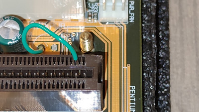
I decided to remove all insulation and simply stay with the little cable that change the VID3 (B119 pin on the Slot 1 socket) from 1 to 0 (grounded) and all other CPU pins withous insulation.

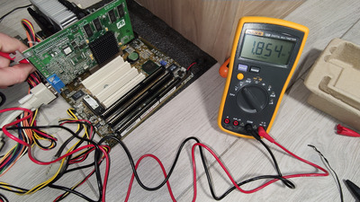
As you can see from the table here, I am using this Coppermine now with 2,05v.

Voltage VID4 VID3 VID2 VID1 VID0
A121 B119 A119 A120 B120
1.80 0 0 1 0 1
1.85 0 0 1 0 0
1.90 0 0 0 1 1
1.95 0 0 0 1 0
2.00 0 0 0 0 1
2.05 0 0 0 0 0
No Core 1 1 1 1 1
2.10 1 1 1 1 0
2.20 1 1 1 0 1
2.30 1 1 1 0 0
2.40 1 1 0 1 1

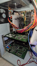
I know, could be dangerous for my processor, but it is active cooled with a big heatsink on it, I don't really think it can be overheat in this situation. You can see the photo about my heatsink and fan on the CPU.

I didn't want to lower the FSB to 112mhz and have the CPU running to 780mhz from the 700mhz original, I wanted the great 933mhz speed.

Now, with 2,05v. the Prim95 is stable even after 15mins.

I will see if I have no more crashes, this is what I hope to.

I want to stay with my P2B at 133mhz, using video cards that can support the 89mhz of AGP without sideband addressing.

I will let you know, but raising the voltage from 1,95 to 2,05 make the situation promising, seems really stable now.

Resuming, my Cb0 stepping processor wasn't booting at 1,8v. raising to 1,85v. I had every time a correct boot. But lot of crashes. 1,95v. seems stable, but playing I had sometimes crashed and returning to desktop, and Prime95 failed after 1 mins. Now with a high voltage of 2,05. we'll see.

Long life to Asus P2B and my Coppermine 700/100/256/1,65!!!

Attachments

  • 1678801915369.jpg
    Filename
    1678801915369.jpg
    File size
    402.42 KiB
    Views
    566 views
    File comment
    asus p2b and this big heatsink for this Coppermine P3
    File license
    Public domain

Computer lover since 1992.
Love retro-computing, retro-gaming, high-end systems and all about computer-tech.
Love beer, too.

Reply 72 of 74, by rasz_pl

User metadata
Rank l33t
Rank
l33t

Instability might be caused by Vtt - 1.5V signal termination. "photoshop bug"
https://www.eecis.udel.edu/~portnoi/asusreworkguide.html
Fixing ASUS P2B freezes on memtest86+ modulo 20 test

Open Source AT&T Globalyst/NCR/FIC 486-GAC-2 proprietary Cache Module reproduction

Reply 73 of 74, by biessea

User metadata
Rank Member
Rank
Member
rasz_pl wrote on 2023-03-14, 21:45:

Instability might be caused by Vtt - 1.5V signal termination. "photoshop bug"
https://www.eecis.udel.edu/~portnoi/asusreworkguide.html
Fixing ASUS P2B freezes on memtest86+ modulo 20 test

My system is stable with 2,05v. Now.

No other problems, the link you gave me speaks about Asus p2b-ls board.

I have the first one p2b rev. 1.o2

Computer lover since 1992.
Love retro-computing, retro-gaming, high-end systems and all about computer-tech.
Love beer, too.