VOGONS


First post, by Hirsch

User metadata
Rank Newbie
Rank
Newbie

This isn't the first thread regarding this topic, but I didn't want to necro them. So I'm opening a new one.

I found a mod from Anthony adding a DVI port to Voodoo graphic cards posted on different websites like this:
https://www.3dfxzone.it/enboard/topic.asp?TOPIC_ID=34099

The picture shows the mod for a Voodoo 4. According to one post on Anthonys Facebook site regarding this mod all Voodoo cards have the same DVI out schematic. My question is: Has anybody adopted the mod for a Voodoo 5 5500 PCI? I'm looking for a schematic. A highres-photo of a Voodoo 5 5500 PCI would help, too.

My "normal" Voodoo 5 5500 looks like this:

Attachments

Reply 1 of 7, by snufkin

User metadata
Rank Oldbie
Rank
Oldbie

I've done a comparison using the photos from PCI Voodoo 5500 moddable to add DVI port? between the Mac version (with DVI). I've marked up components that have changed (or at least the ones I've noticed), including R21 and R34 which aren't fitted to the Mac version. I haven't marked up the component values, but between the drawing you found, and the SiI164 datasheet ( http://www1.futureelectronics.com/doc/SILICON … SII164CTG64.pdf , pdf pages 23-30 probably most helpful) it should be possible to work those out. There seem to be a lot fewer capacitors than the drawing you found, maybe there are some pads on the back of the board?

voodoo_5500_DVI_Changes.jpg
Filename
voodoo_5500_DVI_Changes.jpg
File size
91.96 KiB
Views
937 views
File license
Fair use/fair dealing exception

(oh, I didn't mark the SiI DVI chip, or the connector)

Reply 2 of 7, by Hirsch

User metadata
Rank Newbie
Rank
Newbie

Thank you very much for the information and sorry for the delayed reply (I was on a weekend trip). You are right that there are some unpopulated pads on the back side of the Voodoo 5 5500. I'll work this out and send an update in this thread once I've finished it. A highres photo of the back side of a Voodoo 5 5500 PCI with DVI would help if someone can provide it. I took a photo of my unpopulated V5:

Attachments

Reply 3 of 7, by snufkin

User metadata
Rank Oldbie
Rank
Oldbie

"This won't take long" I thought. Just match up components, how hard can it be. Just enough differences between V4 and V5 to make things interesting. I've based all of this on comparing the photos of the VoodooMac and Voodoo5 PCI from http://www.tdfx.de/eng/grafikkarten_alle.shtml

Usual unhelpful disclaimer that I don't have this board, I haven't tested this mod, I don't think it'll blow anything up, but there are at least 2 resistors I don't understand the purpose of, and it's not like this has been through a design review. Also notice that the pictures of the back of the board are mirrored as it made working out the connections easier, but I forgot to reverse it back before labeling things up. That said:

V5_DVI_Probable_Components.jpg
Filename
V5_DVI_Probable_Components.jpg
File size
406.45 KiB
Views
812 views
File license
Fair use/fair dealing exception
V5_DVI_Component_Change.jpg
Filename
V5_DVI_Component_Change.jpg
File size
413.31 KiB
Views
812 views
File license
Fair use/fair dealing exception

I've tried to keep the colour coding for what I think are the probable components the same as on the V4 mod in the link you originally posted. There are a few differences that might be important. In no particular order:

  • R579 not fitted on V5. They seem to have changed HPD, so it now uses the MSEN output from the SiI (pin 11).
    That uses R23, datasheet says it should be 5k (I think, assuming R23 is the pull up for the MSEN line that the SiI connects to ground to signal monitor presence).
    I'm unclear if the top surface components for HPD (R1 & CR11) now actually do anything. Or indeed any of the HPD components, since MSEN is triggered by if there's a load on the output, not by the HPD signal.
  • Changed Fuse from V4 mod. I think DVI only allows 50mA on DDC +5V, and the fuse fitted to the mac V5 is marked 05, which I think is a SMD005F PTC.
  • No idea what R21 does. It might be the 22ohm resistor on the V4 mod.
  • No idea what R34 does, but it's not fitted on the photo of the mac V5.
  • I think pin 1 of the 3V3 regulator is nearest C3, but best check that pin 4 connects to the various PVcc components. If you start looking for alternative regulators then mind the pinout; I had a quick look and couldn't just find any that fitted. Pins 2&5 need to be Ground.
  • I've marked the diodes as BAV99 (a dual version that will clamp the DDC inputs to the Gnd and +ve supplies on the V5), but I think the one on the HPD signal is actually a single diode BAS16. Doesn't make any real difference.
  • 4052 switch was changed from a CD4052 on V4 to HCT4052 on V5. Don't think it matters as this is just selecting which port to connect to DDC data and clock.
  • Resistor values around the SiI don't match the data sheet, but I've gone with the V4 mod values since I assume they work. Values from datasheet are in the SiI pinout description below.
  • pins 36-47 should really be grounded (by the datasheet), but they're just N/C.

I think the rest makes sense.

If you're interested, the SiI is configured as:

  • no I2C control (ISEL low),
  • 12 bit bus (BSEL low),
  • dual-edge clocked (DSEL high),
  • primary clock edge falling (EDGE low),
  • clock deskew enabled (DKEN high),
  • deskew set to 101b (DK[3..1]) so clock edge is delayed by 0.2 to 0.35nS.
Silicon Image SiI164 pinout, using resistor values as given in the datasheet reference design
1 - Vcc -
2 - DE - data input enable input, high display active, low during blanking time (flyback?)
3 - Vref - Input voltage swing, connected to 3.3V inner plane?
4 - Hsync - Hsync input
5 - Vsync - Vsync input
6 - DK3 - Deskew3 - high via R563 (33k) (optional low via R562), Input deskew 101b = +0.2 to +0.35nS
7 - DK2 - Deskew2 - low via R20 (0k) (optional high via R13)
8 - DK1 - Deskew1 - high via R12 (33k) (optional low via R19
9 - Edge - primary IDCk+ edge is falling edge - low via R560 (330R) (optional high via R561)
10 - PD# - Always powered up - high via R11 (33k) (optional low R18)
11 - MSEN - Monitor Sense output line, pulled high via R23
12 - Vcc - decoupled through C573
13 - Isel - I2C disabled when low via R558 (optional high via R559)
14 - Dsel - DualEdge on IDCk+ high via R556 (2.2k) (optional Low via R17, I2C via R555)
15 - Bsel - dual clocked 12 bit bus, low via R10 (330R) (optional high via R557, I2C via R7)
16 - GND - Ground
17 - PGND - PLL Ground
18 - PVcc1 - PLL 3.3V decoupled via C12, C16 and C577, and L10 also goes to pin 49 PVcc2
19 - ExtSw - voltage swing adjust, external monitor so high via 510R R5
20 - AGnd - Ground
21 - TxC- -
22 - TxC+ -
23 - AVcc - decoupled via C6, C9, C10 and L9. Also goes to pin 29
24 - Tx0- -
25 - Tx0+ -
26 - AGND -
27 - Tx1- -
28 - Tx1+ -
29 - AVcc - see pin 23
30 - Tx2- -
31 - Tx2+ -
32 - AGND -
33 - Vcc - decoupled via C578
34 - Resv - datasheet says must be low, here via R3
35 - DKEN - Deskew inputs DK3..1 when pulled high via R578 (33k) (optional low via R2)
36 - D23
.....
47 - D12
48 - GND -
49 - PVcc2 - see pin 18
50 - D11
.....
55 - D6
56 - IDCk- - In DualEdge mode, so pulled low via R577
57 - IDCk+ - Input Data Clock, triggering on both rising and falling edges
58 - D5
.....
63 - D0
64 - GND

Reply 4 of 7, by Hirsch

User metadata
Rank Newbie
Rank
Newbie

Thank you very much again. I'll give it a try and post an update here. I agree that this mod shouldn't blow up anything. Worst case is that it does not work. In this case I'll have a closer look to the differences you mentioned. I think that my update will take some time because I'll do some test soldering with a cheap LQFP-64 chip on a breakout board and I'll need some time to order the components.

Reply 5 of 7, by Backfire_67

User metadata
Rank Newbie
Rank
Newbie

Hey 😀

Meanwhile it is done and works well. I successfully upgraded a Voodoo 5 5500 PCI with DVI connection.
And it is absolutely safe to replicate.

Some days ago I posted in Voodooalert This Thread related to this topic.
Stick to this parts list - it will work for sure.

Filename
V5 DVI Upgrade Rv2.1.pdf
File size
139.52 KiB
Downloads
72 downloads
File license
Public domain

- Backfire -

Repair of 3dfx Devices and Soundcards with passion...
Here you can find more

Reply 6 of 7, by snufkin

User metadata
Rank Oldbie
Rank
Oldbie

Nice, looks like we ended up with pretty much the same changes. I was just working from some photos, and yours works, so probably best to go with your values.

The only differences I can see are:
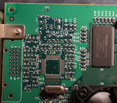
R5 - I went with the 510R from the datasheet. I think yours (430R) gives a slightly higher drive strength, probably good if using long cables.
R23 - I had 5k as the pull up from the datasheet, but your 4.7k only increase the drive current needed by a tiny amount.
R21 - I couldn't see the value in the photo of the Mac v5 board I had, so guessed based on the v4 mod. Only 50% out (I had 100R, you have 220R). Any idea what this one does?
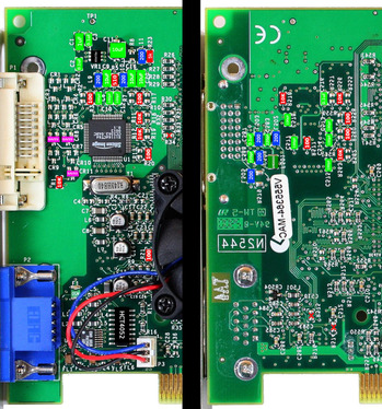
Fuse - I went with 50mA based on that's the max that any connected DVI device is supposed to draw, but then the VESA spec apparently says that the host should limit the current between 50mA and 1A. I didn't know what the v5 could actually supply, so erred on the low side.
Couple of capacitors around the regulator - I just guessed based on the v4 mod, you'll have been able to actually measure them. The datasheet for the regulator doesn't say what should be used, and it won't be a high current load.

If you don't mind, I've a question about the HPD signal. I think that the v4 used the actual HPD signal from the connector, but that v5 uses the Monitor Sense signal on the Sii chip, which it generates based on detecting a load on the signal pins. So I'm not sure if any of the components on the HPD (R1, CR11, L505) are needed or not. Would you be willing to see if the board still works properly, particularly detecting if a monitor is plugged in, if those are removed?

Also, were you able to find a source for the PQ1R33 regulator? I couldn't find them, and the pinout is different from any regulators in that package that I could find.

[edit: forgot to say, interesting that 3dfx stuck with their 100R/10K pull down/up on most of the SII pins, when the datasheet gives 330R/33k]
[edit: oh, and feel free to take any of the diagrams if you think they'd be useful]

Reply 7 of 7, by Backfire_67

User metadata
Rank Newbie
Rank
Newbie

The whole thing was triggered by a friend who wanted to have a V4 4500 AGP converted to a 4800 AGP, which I did immediately.

As a result, a momentum started to build up in the forum and someone started to find out all the components needed for the DVI extension from pictures. But we know that this is indeed guesswork when it comes to capacitors.

It happened that I had a Voodoo 5 5500 PCI MAC here for repair whose owner had allowed me to measure everything on the components. So I did and this list came into being. It is based on a V5 5500 PCI MAC and except for a few components it is the exact values. 3.3µF MLCC are more unusual values than 10µF. That is why we chose 10µF.
The original Sharp fixed voltage reference is indeed hard to get. I have a good private contact, due to my job, in Malaysia and through them I was able to get 50 pieces from old stocks. The part itself is discontinued.

At the moment, I have several Voodoo 5 5500 PCIs that I am supposed to upgrade to DVI. I would like to try out whether R1, CR11 and L505 are important. But they are equipped on the original MAC.

Well then 😀

- Backfire -

Repair of 3dfx Devices and Soundcards with passion...
Here you can find more