VOGONS


First post, by yzbq11c

User metadata
Rank Newbie
Rank
Newbie

Hi, new to the board!
I've wound up reading many Vogons threads in trying to bring my childhood 486 back on line but I'm at a point where I could use some new ideas or perspectives.

Short story is that ~9 months ago I pulled my family's old 486 out of the attic and powered it up. It worked perfectly as if no time had passed, very cool.

I took it home and stored it until I had some time to tinker. I recently pulled it and powered it up to be met with a host of issues.

So i stripped it down to just the board, ram, and processor and would receive a 3-long, 2-short beep error code when powering up.

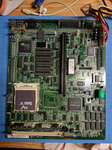
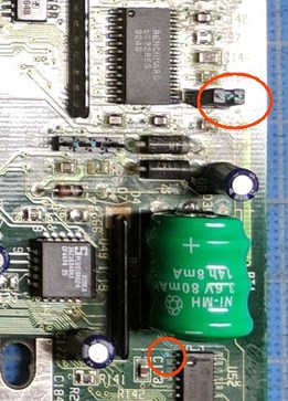
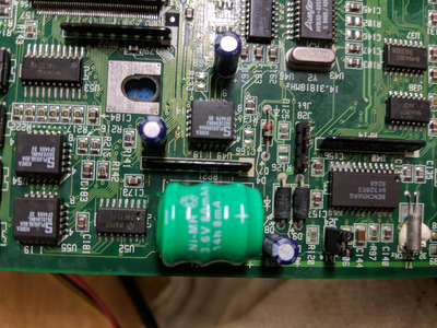
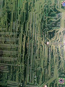
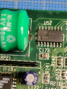
I could see the barrel battery had begun leaking, so in my first attempt w a solder iron, i replaced the battery and cleaned what I could, see the attached photo of the post-cleaned board (i've already been told this job could have been better, so its on the short list of things to revisit)

As i said, the board wouldn't POST and I would run up against the 3-2 beep errors. I couldn't identify the board or the error codes but a common answer was that the memory wasn't mounting. I bought some memory from ebay (128MB (2 X 64MB) EDO MEMORY NON PARITY 60NS SIMM 72 PIN 16X32) and when installed the beeping stopped but I still didn't seem to mount. I would get no video output in this configuration.

Now for the really ugly stuff:

It was recommended I pick up a diagnostic card to better identify the errors. I bought one and it just didn't seem to do anything when inserted into the ISA slot. So, like an ass, I inserted the PCI end of the diagnostic card into the ISA slot and immediately part of the card lit up but also started smoking. I only did this once, but the motherboard now seems in worse shape: Now, even with the memory modules removed I get NO beeping error codes, no video.

I've reinserted several cards, removed the processor, plugged in a bunch of peripherals in an attempt to get something different to happen, but no luck.

Does anyone have suggestions for working through the next part of this? I am by no means an electrical person, and am fumbling through this as a hobbyist trying to get a piece of nostalgia to life.

Any help and suggestions appreciated. Happy holidays!

Attachments

Reply 1 of 13, by Horun

User metadata
Rank l33t++
Rank
l33t++

Looks like a Packard Bell 430 motherboard or similar...
I can see a corroded jumper and at least one bad "via" that should have been fixed during the battery fix....
Too bad about the Diag card, Probably ruined it and maybe the motherboard 🙁

Attachments

  • Image1.jpg
    Filename
    Image1.jpg
    File size
    37.9 KiB
    Views
    611 views
    File license
    Public domain

Hate posting a reply and then have to edit it because it made no sense 😁 First computer was an IBM 3270 workstation with CGA monitor. Stuff: https://archive.org/details/@horun

Reply 2 of 13, by snufkin

User metadata
Rank Oldbie
Rank
Oldbie

Have you got photos of the front and back of the board, after the mishap? Maybe the test card has shorted power pins on the slot, causing high currents on the motherboard PCB power traces, so you may be able to see some heat damage. Also, do you have a multimeter? It'd be useful to be able to test for voltages and resistances.

Reply 3 of 13, by yzbq11c

User metadata
Rank Newbie
Rank
Newbie
snufkin wrote on 2021-12-19, 20:10:

Have you got photos of the front and back of the board, after the mishap? Maybe the test card has shorted power pins on the slot, causing high currents on the motherboard PCB power traces, so you may be able to see some heat damage. Also, do you have a multimeter? It'd be useful to be able to test for voltages and resistances.

Attached are some photos taken today. I also re-removed the battery and attempted to clean the area again, including the areas highlighted by Horun above. Still nothing.

I do have a multimeter but am not totally sure about what i'm looking at. I am able to detect flow from the ISA slot's end slots and can't see any evidence of burn. But again, i'm not sure how to 'read' the multimeter, I can just see something is connecting when i touch each sections respective end slots.

Attachments

  • battery.jpg
    Filename
    battery.jpg
    File size
    890.9 KiB
    Views
    556 views
    File license
    Public domain
  • back.jpg
    Filename
    back.jpg
    File size
    1.26 MiB
    Views
    556 views
    File license
    Public domain
  • back-isa.jpg
    Filename
    back-isa.jpg
    File size
    1.33 MiB
    Views
    556 views
    File license
    Public domain

Reply 4 of 13, by Disruptor

User metadata
Rank Oldbie
Rank
Oldbie
yzbq11c wrote on 2021-12-19, 15:52:
Hi, new to the board! ... As i said, the board wouldn't POST and I would run up against the 3-2 beep errors. I couldn't identif […]
Show full quote

Hi, new to the board!
...
As i said, the board wouldn't POST and I would run up against the 3-2 beep errors. I couldn't identify the board or the error codes but a common answer was that the memory wasn't mounting. I bought some memory from ebay (128MB (2 X 64MB) EDO MEMORY NON PARITY 60NS SIMM 72 PIN 16X32) and when installed the beeping stopped but I still didn't seem to mount. I would get no video output in this configuration.
...

Welcome!

Since it is unusual that a 486 mainboard supports EDO DRAM you should try FPM DRAM instead.

I'm sorry, I can't help you with the ugly stuff.

Reply 5 of 13, by Eep386

User metadata
Rank Member
Rank
Member

Welcome to Vogons!
The corrosion on the bq3285S pins possibly has something to do with it, that's the RTC chip.
With no or inaccessible RTC, the system will not POST.

I also see a few traces that appear eaten away 🙁

Life isn't long enough to re-enable every hidden option in every BIOS on every board... 🙁

Reply 6 of 13, by yzbq11c

User metadata
Rank Newbie
Rank
Newbie
Eep386 wrote on 2021-12-19, 21:38:
Welcome to Vogons! The corrosion on the bq3285S pins possibly has something to do with it, that's the RTC chip. With no or inacc […]
Show full quote

Welcome to Vogons!
The corrosion on the bq3285S pins possibly has something to do with it, that's the RTC chip.
With no or inaccessible RTC, the system will not POST.

I also see a few traces that appear eaten away 🙁

Do you mind pointing them out Eep386? I've tested a bunch of ugly looking traces around the battery but they seem to flow via a multimeter, but i'm not a pro at spotting them. Thanks!

Disruptor wrote on 2021-12-19, 21:35:

Since it is unusual that a 486 mainboard supports EDO DRAM you should try FPM DRAM instead.

Any memory configuration no longer produces beeping but I did order some FPM anyway, thanks Disruptor!

Reply 7 of 13, by snufkin

User metadata
Rank Oldbie
Rank
Oldbie

Had a look on Ultimate Retro, and it looks like the motherboard is a Packard Bell PB430: https://www.ultimateretro.net/en/motherboards/8734
That led to here: http://www.uktsupport.co.uk/pb/mb/430.htm
Which says it doesn't support EDO, but looks like it has some RAM soldered on it, those chips marked 814400H-70 in the corner near the battery (8 chips at 4Mb each, so 4MB on board). So the board should always be able to have some working RAM. Apparently it's a Phoenix BIOS, so 3 long-2 short might be 1-1-1-2. But I can't find that listed anywhere.

There is a 1-1-3 listed, which is a CMOS read/write fail, which could be battery related: http://www.uktsupport.co.uk/pb/mb/phnxcode.htm

I think the first thing to check is that you're getting the right voltages on the board, or at least at the ISA slot. Take everything out (including CPU), plug in the PSU and turn on. On your multimeter select DC voltage (depending on the meter, set the range to around 20V). Hold the black probe on some that's Ground (black pin on any molex power connector, or the shields of any of the ports at the back, are probably convenient). Then, using the ISA pinout from here: https://upload.wikimedia.org/wikipedia/common … SA_Bus_pins.svg , hold the red probe on pins B3 (+5V), B5 (-5V), B7 (-12V) and B9 (+12V) and see what the meter shows. I think the only really important one right now is the +5V.

There are a few tracks on the top near the battery that look in a bad way, and there's a track near one of the battery solder points on the back that looks like it's been broken, but they can be repaired. But it's also possible that something important broke. When you say the post card didn't seem to do anything, did it do anything, like any status lights?

Reply 8 of 13, by Horun

User metadata
Rank l33t++
Rank
l33t++

Agree !
Back of the board looks good ! The very small traces that are very dark near the battery look bad. Use a Ohm meter and check the traces...if over a few ohms then they need fixing.
Yes the solder joints on the RTC look corroded and need cleaning (toothbrush and vinegar works)...
That board is a P. Bell PB430 (or 440, they use same board) and already has 4MB on board so you do not need the SIMMS to make it boot and yes the SIMMS must be FPM either 8 chip or 9 chip type (board does not have parity enabled by default).
added: Just make sure J41 has a jumper or onboard ram is disabled. It looks like your board has the jumper but is not on correctly...
I have the same board (just pulled it out of storage) but a rev D.0 , think yours is a Rev E or F but is exact same. The back sticker with 180435 is the give away, same sticker on mine and same exact BIOS label too....

Attachments

  • battery work.jpg
    Filename
    battery work.jpg
    File size
    490.95 KiB
    Views
    506 views
    File license
    Public domain

Hate posting a reply and then have to edit it because it made no sense 😁 First computer was an IBM 3270 workstation with CGA monitor. Stuff: https://archive.org/details/@horun

Reply 9 of 13, by yzbq11c

User metadata
Rank Newbie
Rank
Newbie

Snufkin:
Yes! The board is from a Packard Bell and I found a mark of 430. Awesome, thanks for linking these resources! Some FPM memory is on the way.
I checked the voltage on the ISA slot and things look pretty close to the way they should be, readouts as follows:
- B3: +5.01
- B5: -4.97
- B7: -12.36
- B9: +12.2

How exact should these numbers be? Is it an issue that B5 doesn't make the full -5? They seem pretty close otherwise.

As for the diag card, tested it again and yes, no lights, no digits, no life to the diag card at all. Maybe was always dead, but the small nub where the PCI end of the diag card begins never allows a totally full seating of the card into the ISA slot. I've begun the replacement process just to be sure.

Horun:
Attached is a closer pic of what I think everyone is pointing out as the suspect traces, is that correct? These dark lines? If you have a good video showing the test method I'd love to watch but I'll hunt around YT as well, thank you.

As for the J41 jumper, I fixed it so it spans both pins but no difference. Also left it completely open, no difference.

I found a small marking on the back that also labels my board a rev D.0!

Thank you all for your help! Vogons seems like an awesome community!

Attachments

Reply 10 of 13, by Disruptor

User metadata
Rank Oldbie
Rank
Oldbie
yzbq11c wrote on 2021-12-20, 14:07:
- B3: +5.01 - B5: -4.97 - B7: -12.36 - B9: +12.2 […]
Show full quote

- B3: +5.01
- B5: -4.97
- B7: -12.36
- B9: +12.2

Voltage levels are just fine.

Reply 11 of 13, by snufkin

User metadata
Rank Oldbie
Rank
Oldbie
yzbq11c wrote on 2021-12-20, 14:07:
I checked the voltage on the ISA slot and things look pretty close to the way they should be, readouts as follows: - B3: +5.01 - […]
Show full quote

I checked the voltage on the ISA slot and things look pretty close to the way they should be, readouts as follows:
- B3: +5.01
- B5: -4.97
- B7: -12.36
- B9: +12.2

How exact should these numbers be? Is it an issue that B5 doesn't make the full -5? They seem pretty close otherwise.

Yeah, +/-5% is ok. Shame really, as that was something easy to check and possibly fix.

As for the diag card, tested it again and yes, no lights, no digits, no life to the diag card at all. Maybe was always dead, but the small nub where the PCI end of the diag card begins never allows a totally full seating of the card into the ISA slot. I've begun the replacement process just to be sure.

Sorry, I meant from before it got broken, when you had it plugged in using the ISA connector?

I've got a nasty feeling that the chipset (big ACC Micro chip) may have been fried. The ISA and PCI pins don't line up, so putting the PCI connector in the ISA slot might have shorted together pairs of the ISA pins, which would allow things like -12V to connect to the DRQ2 pin. Or, worse, connected one of the ISA power pins to the PCI card Ground, which would then appear on all the PCI card Ground pins and be connected to whichever ISA pin they were touching. I think that the earlier problems where quite likely from the battery corrosion, but the fact that things suddenly got worse (no beeps at all) after the ISA/PCI mixup suggests that something new got broken then.

But, you might get lucky, so see if other suggestions help. Maybe it is a RAM problem, so wait for the FPM memory, fit it and disable the onboard memory and see if anything happens.

Quick description for using the multimeter to check connections: Unplug things from the board (ideally remove the battery). Put the meter in resistance/ohms mode (I generally put my cheap meter on 2000 ohm range when hunting for connections/shorts, 200 ohm range is more precise but a bit slower to respond). Find a trace that looks a bit gappy and try to visually trace both ends of the gap back to something metal. Then put probes (either way round, doesn't generally matter when checking for direct/short connections) on those two bits of metal and see if you get a reading. A short should measure about the same (within an ohm) as connecting the probes directly to each other (this isn't necessarily 0, but should be close to it).

If you can't find anything metal that the trace connects to then you can carefully scrape back a little bit of the lacquer covering the track to expose the copper, then cover the copper back over with a little bit of varnish/nail polish/anything to stop is oxidising.

Reply 12 of 13, by Disruptor

User metadata
Rank Oldbie
Rank
Oldbie

I have a 486 mainboard (486PVI-SP3G) that runs an emergency procedure with EDO DRAM installed:
It starts an emergency BIOS, called "boot block".
I've found this out because it does access floppy disk drive but there was no picture on the screen.
Later I have seen that I just need an ISA graphics card that is stupid enough and does not to be initialized by the VGA BIOS.
(This graphics card also writes POST codes on screen on my 386sx with QuadTel BIOS.)
Well, it is a TVGA8900C based graphics card. (Why the heck do I still have Trident graphics cards? They all are so slow!)

Reply 13 of 13, by Eep386

User metadata
Rank Member
Rank
Member

My Trident 8900Ds take personal exception to that 'they are all so slow' statement. 😜
All kidding aside, Tridents have the knack of coming in really handy as they are some of the *least* picky ISA VGA cards you can find, and they're still relatively plentiful as far as vintage PC hardware goes.

Some of the newer 486 boards have Award BootBlock BIOS, which is indeed quite nice to have when a BIOS flash goes off. My own Shuttle HOT-433 directly supports EDO but doesn't seem to do anything special with it, returning identical access times to FPM.

Life isn't long enough to re-enable every hidden option in every BIOS on every board... 🙁