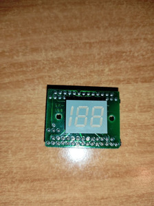
Hello, I just got a case with 2 digits turbo display, but I never messed with it and I would need some help about how it works.
Actually it shows always 30 when the turbo button is pushed or not.
I tried to find so called HY-103 but without any success.
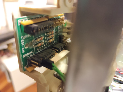
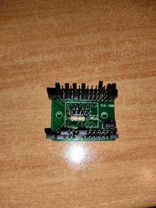
Sorry for the bad pictures but that thing won't come off from the case.
Those displays are cool, but they just show a static number that you set with jumpers. Try this link and try to match up your model for help on figuring out how to set the jumpers.
It seems your kind of speed display is not mentioned on http://www.minuszerodegrees.net/led_speed_dis … eed_display.htm . The wire connector on the "normal 5" jumper position looks strange. I can only guess some of the information you need to make proper use of the display, because I don't see the most important stuff.
What I do see:
There are separate jumpers for "Turbo" and "Non-Turbo" to configure the displayed speeds.
The number 1..7 seem to indicate the individual 7 segments of the tens and the ones digit.
Most likely, the jumpers directly close the circuit, so a jumper that is set turns on the corresponding segment, a jumper that is removed turns off the corresponding segment.
In the Turbo block, one digit has all jumpers set (it will display as "8"), and the other digit has all jumpers removed (it will display blank). This seems to indicate that the display used inverse logic compared to the mainboard and the system that was originally in that case displayed "8" non-turbo mode.
Obviously, the left jumpers are for the ones display, and the right jumpers are for the tens display.
In the "normal" block, in the tens section, two jumpers are not set. This matches your observation that the tens section displays a "3".
In the "normal" block, in the ones section, one jumper is open and one jumper position has a cable connected. As you say the ones display is "0", which has only a single segment turned off, the cable seems to behave similar to an installed jumper.
Thus I conclude that the display currently displays what you set in the "normal" section
The most important question is, though, how does the display know whether the system is in turbo mode or not. This information is received via some pins in the bottom right block. To make an educated guess on how that block is to be connected, I would need to know all the letters next to the pins, not just the "O", the "S" and the letter that might be a one or an "I".
As your display is displaying something, it seems the power is connected correctly, so you can assume that the pins the power supply is currently connected to are indeed for connecting power.
mkarcherwrote on 2021-12-28, 16:02:It seems your kind of speed display is not mentioned on http://www.minuszerodegrees.net/led_speed_dis … eed_display.htm . The wi […] Show full quote
It seems your kind of speed display is not mentioned on http://www.minuszerodegrees.net/led_speed_dis … eed_display.htm . The wire connector on the "normal 5" jumper position looks strange. I can only guess some of the information you need to make proper use of the display, because I don't see the most important stuff.
What I do see:
There are separate jumpers for "Turbo" and "Non-Turbo" to configure the displayed speeds.
The number 1..7 seem to indicate the individual 7 segments of the tens and the ones digit.
Most likely, the jumpers directly close the circuit, so a jumper that is set turns on the corresponding segment, a jumper that is removed turns off the corresponding segment.
In the Turbo block, one digit has all jumpers set (it will display as "8"), and the other digit has all jumpers removed (it will display blank). This seems to indicate that the display used inverse logic compared to the mainboard and the system that was originally in that case displayed "8" non-turbo mode.
Obviously, the left jumpers are for the ones display, and the right jumpers are for the tens display.
In the "normal" block, in the tens section, two jumpers are not set. This matches your observation that the tens section displays a "3".
In the "normal" block, in the ones section, one jumper is open and one jumper position has a cable connected. As you say the ones display is "0", which has only a single segment turned off, the cable seems to behave similar to an installed jumper.
Thus I conclude that the display currently displays what you set in the "normal" section
The most important question is, though, how does the display know whether the system is in turbo mode or not. This information is received via some pins in the bottom right block. To make an educated guess on how that block is to be connected, I would need to know all the letters next to the pins, not just the "O", the "S" and the letter that might be a one or an "I".
As your display is displaying something, it seems the power is connected correctly, so you can assume that the pins the power supply is currently connected to are indeed for connecting power.
Thank you for your precious clarification.
Indeed the display shows 30 (the cpu is a 300 mhz, so it makes sense the choice), but the showed frequency doesn't change if the turbo button is pressed.
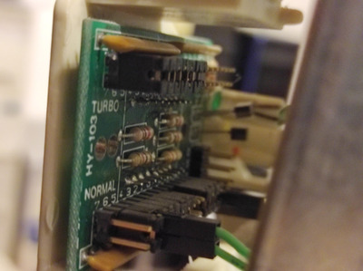
I was able to take a better picture:
Do you have idea of what the O S T connectors mean?
Thank you.
Edit: by any chance, do you know if there is a easy way to change that circuit board with a 3 segments turbo led? Are they available anywhere for a reasonable price?
The most important question is, though, how does the display know whether the system is in turbo mode or not. This information is received via some pins in the bottom right block. To make an educated guess on how that block is to be connected, I would need to know all the letters next to the pins, not just the "O", the "S" and the letter that might be a one or an "I".
As your display is displaying something, it seems the power is connected correctly, so you can assume that the pins the power supply is currently connected to are indeed for connecting power.
Do you have idea of what the O S T connectors mean?
In some turbo displays, "S" is used as input from the mainboard to tell the display whether the system is in turbo mode or not. Often, this is just a single pin. T (as T+ and T-) often is the connection for a dedicated turbo LED (as the mainboard turbo LED output is connected to the speed display, the Turbo LED can't any longer be connected to the mainboard). I have no idea about "O" or "zero".
For a first assesment of pin functions, it would be helpful if you can find out wheter some of the six unused pins are directly connected to ground or +5V.
Edit: by any chance, do you know if there is a easy way to change that circuit board with a 3 segments turbo led? Are they available anywhere for a reasonable price?
Sorry, no idea. I don't even know whether full 3-segement speed displays ever got widespread. "2,5" digits (0-199) were quite common, and should be available. A quick ebay search for "cpu frequency display" showed up some results in russia, but they don't go up to 300.
Edit: by any chance, do you know if there is a easy way to change that circuit board with a 3 segments turbo led? Are they available anywhere for a reasonable price?
Try searching for <"3 digit" led display> on ebay. There are a few different sizes (and you would have to figure out what connections to set)
See my graphics card database at www.gpuzoo.com
Constantly being worked on. Feel free to message me with any corrections or details of cards you would like me to research and add.
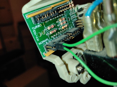
So I did some further test, the display doesn't change the frequency showed when turbo button is pushed because the motherboard lacks the proper pin header (no surprise since it is a ss7 board).
The green wire showed in the picture, it was used because who assembled the pc lacked a jumper, I suppose, since I took it off and put a jumper.
A 2,5" digits (0-199) would suffice, since I will use a 486 board, but still I'm not comfortable to order something outside EU since the new import duties are unavoidable.
Thank you all for the tips, I will update the situation after switching the motherboard.
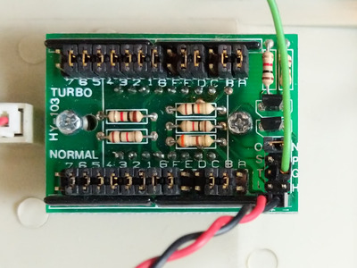
Hello. I have the same type of display and need a bit of help.
What I already understand:
The 2-pin header labeled +/- is for power (red/black wire in the pic)
The segmented LED is configured to display either 20 MHz in normal operation or 40 MHz in turbo operation.
The G-pin is a single wire (the green one in the pic), which is currently connected to one pin of the mainboard's TB-LED header. So this is probably how the display senses which state the system is in. This is currently working correctly.
What I couldn't figure out yet: How do I connect the 2-pin turbo LED of the case? Since the TB-LED header on the mainboard is now used by the display, I'd assume that there's another TB-LED header on the display PCB...
So using a multimeter, I measured the T-pin against ground, which indeed reads 5V when in turbo mode and only a few mV in normal mode. But the adjacent pins labeled S and L are not directly connected to ground, so I am hesitant in placing the TB-LED header on there...
I have 2 turbo connectors: 3 pins (orange, black and white) and a 2 pin (yellow and white).
This is how I connected the stuff: 3 pins cable from TSW to tb.sw on the motherboard, two pin cable from the led on the case on the motherboard.
The 5v+g on the turbo panel is unconnected.
With this configuration when the turbo switch is pressed (and the led is on) pc goes full speed, when the button is unpressed (led off) goes slow and the led panel shows nothing
If I connect the led to the 5v+g the turbo led doesn't work, the turbo panel shows nothing and the behaviour is the opposite button pressed pc is slow, button unpressed pc goes at rated speed.
I measured the resistance (in circuit) and it showed a value between 38 an 39.
I think the led is broken but not the whole circuit board, markings on the 3 digits led are:
ledtech 14
la4023-14-s1
It's a 16 pin, 3 digits led, what can I buy as replacement?
You absolutely need that 5V connected or there won't be anything getting lit.
Turbo switch is supposed to have 2 sections, one goes to the motherboard's turbo switch header, other to the LEDs to switch between low/high speed display.
Turbo LED output from the mobo goes wholly unused in this case.
You absolutely need that 5V connected or there won't be anything getting lit.
Turbo switch is supposed to have 2 sections, one goes to the motherboard's turbo switch header, other to the LEDs to switch between low/high speed display.
Turbo LED output from the mobo goes wholly unused in this case.
You are right, I stolen the right cable from another case and the led display works now like a charme 😁
Any suggestion where I could get another cable like that? They seem impossible to find
I haven't seen any separate ones with molex on one end and 2pin dupont on other, I always see it coming straight out of PSU itself or already from a nearby molex directly. On some PSUs I have manually added things into the PSU itself.