vetz wrote on 2022-01-02, 20:34:
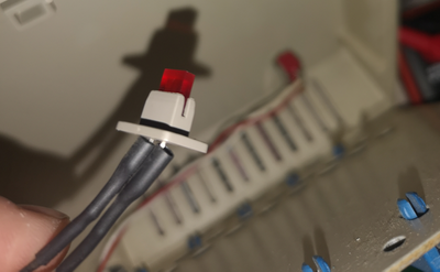
snufkin, I'm a bit worried about going for option 1 as the current LEDs fit perfectly to the sockets in the case. Please let me know if they are totally standard, if that is the case, then this would be a viable option.
Oh, it'll almost certainly be some sort of standard.
Ha, just did the same as Weedeewee. Went to mouser, over 4,500 through-hole LEDs. 'Great' I thought. Select common anode. Results remaining? 13. With rectangular case? 0.
Went to Kingsbright (big LED maker). 0.
Ok, that's probably not an option.
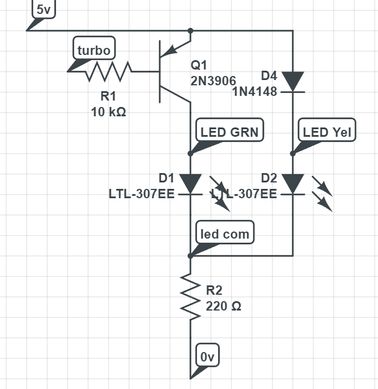
Regarding option number two. From how I read it (please correct me if I misunderstand something), one of the black cables would always be connected to pin 3 (power). That would mean in a turbo OFF scenario the LED would get 5v from both black cables at the same time and that would need to trigger a color switch (or opposite, 5v in both is the standard at turbo ON and gives green color, turning it off would swap to yellow). Do you know how bi colored LEDs would normally behave in such a scenario?
As I understand it (from looking at datasheet, I haven't tried this), there are two LEDs in the package and they can be turned on separately via the +ve side (the two black wires). So there's a Yellow and Green LED, of which you'd have one on permanently as the power LED, then the second added when the turbo was on, which would change the colour. You might need to experiment to find out which combination you preferred (Yellow, then Yellow+Green, or Green, then Green+Yellow). It's a shame the colours are yellow and green, since yellow already has green in it, so the colour shift won't be as big as if it was a red/green LED.
It'd be a bit more work (although not too much, I think) to make it in to a complete change over.
Sure you don't want to go with option 3?
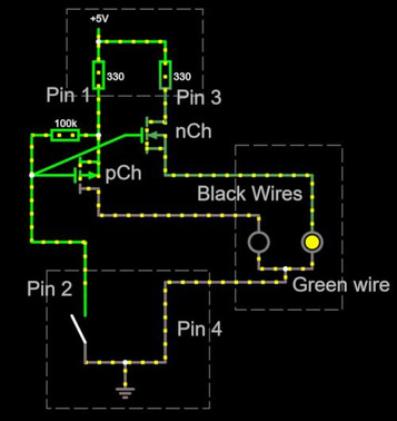
[edit: I think you need one of these: https://uk.farnell.com/diodes-inc/dmc2710udwq … -sot/dp/3828400 and a 100k(ish) resistor. And a bit of fiddly wiring.
No idea if the link will work, but anyway, I had a go at a simple simulation, there's a clickable switch by pin 2:
https://www.falstad.com/circuit/circuitjs.htm … uh5TuS6RlNE1hAA
]
[another edit: It's possible the nCh FET won't turn off enough and whichever colour LED is connected to it might get dimmer but not turn off. Might be able to dump the nCh and just bung a diode from pin 3 to pin 2, so pin 3 gets pulled fairly close to Ground when the turbo switch causes pin 2 to go to ground. Vf on an LED will be lower than Vf on a normal diode. Could even get a schottky to get the Vf lower. Still not perfect, uses more components, not efficient (added diode just burns power when the LED is off) but probably good enough if the first doesn't work:
https://www.falstad.com/circuit/circuitjs.htm … AAuiRGZYGGYB+QA
]