VOGONS


First post, by CachoAlpuy

User metadata
Rank Newbie
Rank
Newbie

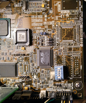
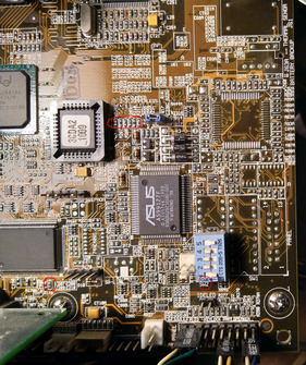
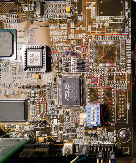
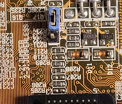
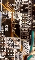
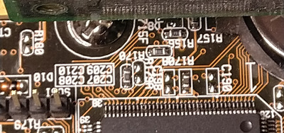
Hi, i have the HP variant of the p3c-d motherboard and im looking forward to make the conversion to the asus p3c-d motherboard so i can use the ASUS Bios, for that reason im looking for high resolution pictures of the following area:
photo5127543704603699959.jpg.

I need to be able to see the resistor values.

Thanks to everyone who can provide something.

Reply 1 of 14, by dionb

User metadata
Rank l33t++
Rank
l33t++

I might be able to, I think I have the retail version.

That said, wasn't the HP version green?

To get you pics good enough to see resistor values I need to use a microscope (no decent camera with macro function), which gives a much smaller field of view than this pic. Could you perhaps indicate exactly which resistors you need?

Reply 2 of 14, by CachoAlpuy

User metadata
Rank Newbie
Rank
Newbie
dionb wrote on 2022-01-20, 15:20:

I might be able to, I think I have the retail version.

That said, wasn't the HP version green?

To get you pics good enough to see resistor values I need to use a microscope (no decent camera with macro function), which gives a much smaller field of view than this pic. Could you perhaps indicate exactly which resistors you need?

Yes, the board is green, than photo was taken from the internet of the retail version.

photo5127543704603699959-1.jpg

This is the zone i need, maybe you can make a picture with a camera and if some values cannot be seen i ask you later.

Thanks!

Reply 3 of 14, by dionb

User metadata
Rank l33t++
Rank
l33t++

Here's the best I can do without the microscope:

IMG_20220121_162137.jpg
Filename
IMG_20220121_162137.jpg
File size
1.65 MiB
Views
1054 views
File license
CC-BY-4.0

Hope it's good enough - I can read most of the SMD stuff ...

Reply 4 of 14, by CachoAlpuy

User metadata
Rank Newbie
Rank
Newbie
dionb wrote on 2022-01-21, 15:28:

Here's the best I can do without the microscope:

IMG_20220121_162137.jpg

Hope it's good enough - I can read most of the SMD stuff ...

It looks perfect, i will start spotting the differences, maybe i ask you some values later.
Thank you!

Reply 6 of 14, by dionb

User metadata
Rank l33t++
Rank
l33t++
pshipkov wrote on 2022-01-22, 05:34:

I tried before but didn't work.
Dionb, did you try to push the vanilla board past its specs ?
133 fsb with tulies at least ?

No, I have two P3-933EB on it running at 133MHz FSB (in-spec). GIven how fragile these P3C-D boards seem to be I don't want to push it. I have enough other ones for that.

Reply 7 of 14, by pshipkov

User metadata
Rank Oldbie
Rank
Oldbie

Altered one of the two HP-Kayak-crippled P3C-D boards here and it does not start now. Kind of expected that, since the last time i tried few years ago on another board resulted in the same issue.
There are 3 areas that i am still unsure about.
@Dionb, can you clarify the values of these elements please, or provide pictures of the areas ?
Maybe this will make the difference.

Attachments

retro bits and bytes

Reply 8 of 14, by CachoAlpuy

User metadata
Rank Newbie
Rank
Newbie
pshipkov wrote on 2022-01-24, 04:14:
Altered one of the two HP-Kayak-crippled P3C-D boards here and it does not start now. Kind of expected that, since the last time […]
Show full quote

Altered one of the two HP-Kayak-crippled P3C-D boards here and it does not start now. Kind of expected that, since the last time i tried few years ago on another board resulted in the same issue.
There are 3 areas that i am still unsure about.
@Dionb, can you clarify the values of these elements please, or provide pictures of the areas ?
Maybe this will make the difference.

Did you remove the HP HW monitoring circuitry?
The eeprom ic is different, i think that the asus one is smaller, maybe you should solder a socket.
Did you add r231a resistor?
Also there is a resistor under the dip switches on the asus that must be removed on the hp board.

Searching on the web i saw that someone made it work removing the hp circuitry and soldering a 256KB eeprom.

Reply 9 of 14, by pshipkov

User metadata
Rank Oldbie
Rank
Oldbie

Stripped the entire HP circuitry.
I already had EEPROM socket in place from previous mods.
Yes, using the ASUS BIOS.
Yes, removed the resistor under the dip switch packages.

Can you point on the picture the other resistors you mentioned ?

retro bits and bytes

Reply 10 of 14, by CachoAlpuy

User metadata
Rank Newbie
Rank
Newbie
pshipkov wrote on 2022-01-24, 19:03:
Stripped the entire HP circuitry. I already had EEPROM socket in place from previous mods. Yes, using the ASUS BIOS. Yes, remove […]
Show full quote

Stripped the entire HP circuitry.
I already had EEPROM socket in place from previous mods.
Yes, using the ASUS BIOS.
Yes, removed the resistor under the dip switch packages.

Can you point on the picture the other resistors you mentioned ?

These are the difference i spotted, some are missing components, some are different values. Maybe there are more components with different values.

Attachments

Reply 11 of 14, by dionb

User metadata
Rank l33t++
Rank
l33t++
pshipkov wrote on 2022-01-24, 04:14:
[...] […]
Show full quote

[...]

There are 3 areas that i am still unsure about.
@Dionb, can you clarify the values of these elements please, or provide pictures of the areas ?
Maybe this will make the difference.

Gave it my best shot again, two out of three look better, but that third one on bottom left is just a blur.

IMG_20220127_204001.jpg
Filename
IMG_20220127_204001.jpg
File size
1.52 MiB
Views
846 views
File license
CC-BY-4.0
IMG_20220127_204026.jpg
Filename
IMG_20220127_204026.jpg
File size
557.77 KiB
Views
846 views
File license
CC-BY-4.0
IMG_20220127_204044.jpg
Filename
IMG_20220127_204044.jpg
File size
1.18 MiB
Views
846 views
File license
CC-BY-4.0

Reply 13 of 14, by MadYoshi

User metadata
Rank Newbie
Rank
Newbie

Hi,
I looking for high-res pictures from the back of the board. Especially the area from the northbridge. ASUS P3C-D or the HP Kayak XM600, it doesn't matter.

Thanks to everyone who can provide something.