VOGONS


First post, by stephen_usher

User metadata
Rank Newbie
Rank
Newbie

I've recently rescued a 486DX-33 machine which is displaying an issue when hard reset, either at boot or when the reset button is pressed. Basically, it's not booting at all.

It's a no-name board but the BIOS string suggests that it was made by "Lucky Star".

When I first got the machine 99% of the time it would not boot when powered on but would as soon as the reset button was pressed. However, after a number of hours of running it usually takes 10s of presses of the reset switch before it will boot. Once it does boot it is completely stable. I can run benchmarks and tests all day and it's as solid as a rock.

Using an oscilloscope on the BIOS ROM /CE pin shows the following sets of activity: None, brief spike down to 0V, square pulse to 0V, drop to 0V followed by two spikes to 5V, drop to 0V and stay there or boot. The BIOS POST diag ISA board shows smetimes the IRDY LED off or dimly glowing (one state per reset) unless the machine boots, in which case there is normal activity.

The PSU power rails are all good and clean (I've recapped the PSU) and power good comes up nicely. As far as I can trace it seems that the reset circuit between the reset switch, power-good circuti and the chipset is operating normally.

It "feels" like it's a capacitor, but there are no electrolytics and I'm not sure the jelly-bean tantalums fail in that sort of way.

So, any ideas?

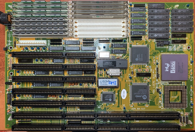
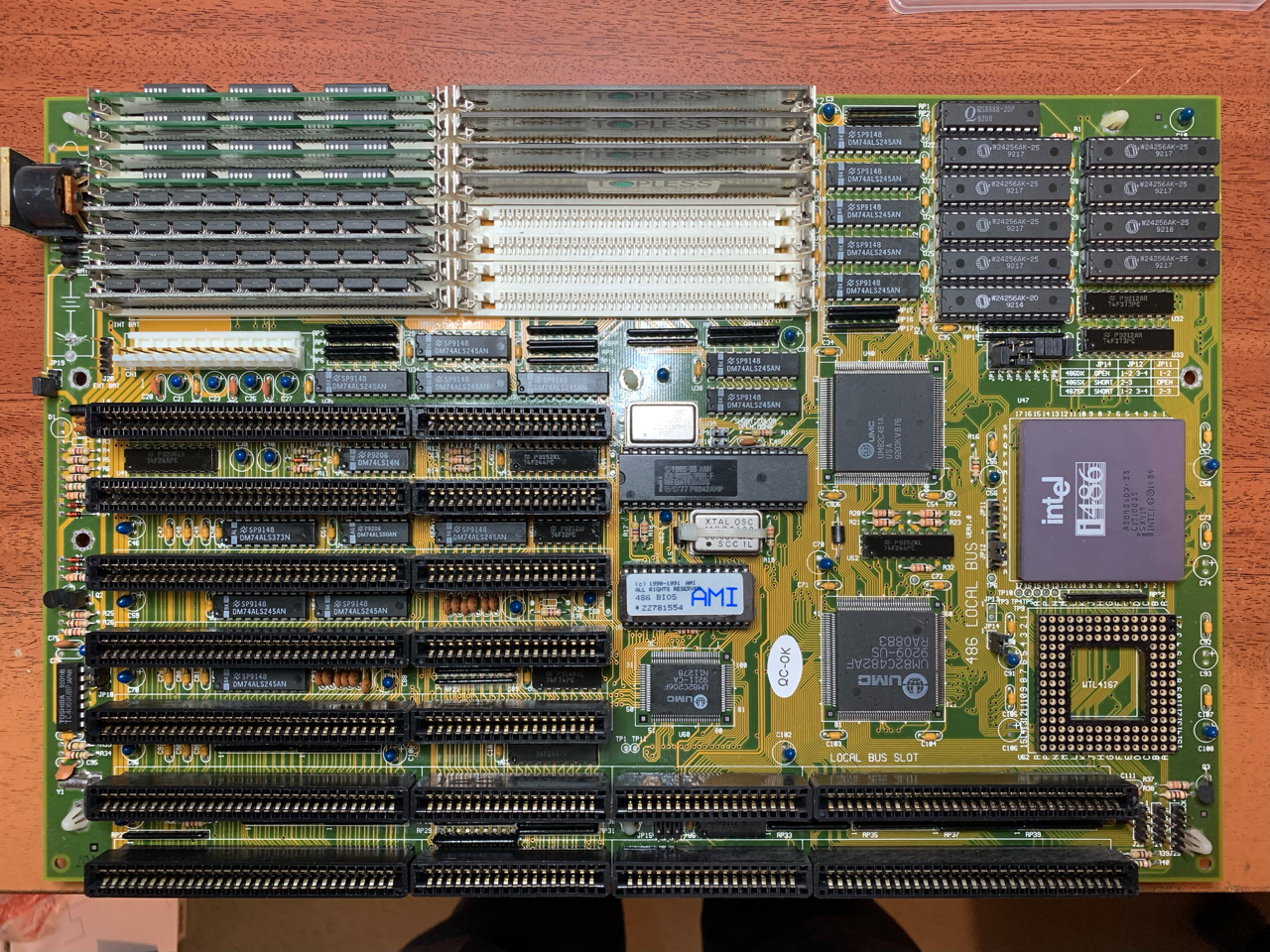
Anyway, here's a picture of the board:

FLA2mTQ000ULNtfx.png
Filename
FLA2mTQ000ULNtfx.png
File size
1.35 MiB
Views
1205 views
File license
CC-BY-4.0

Reply 1 of 20, by Horun

User metadata
Rank l33t++
Rank
l33t++

I would try with just one bank of 4 SIMMS to try an isolate the issue. Mixing 3 chip with 9 chip is usually a no-no on old boards.
Also never saw a UMC chipset that had diff sized logo's on same board but what do I know ;p
A better picture might help....

Hate posting a reply and then have to edit it because it made no sense 😁 First computer was an IBM 3270 workstation with CGA monitor. Stuff: https://archive.org/details/@horun

Reply 2 of 20, by stephen_usher

User metadata
Rank Newbie
Rank
Newbie

I've tried with only one set of SIMMs and the symptoms are the same, whichever set I use. I've also tried the board without any boards in the slots and the behaviour of the /CE pin on the ROM is the same. I've also tried two CPUs, the original 486DX-33 and an Intel 486DX2-66 "Overdrive" and it made no difference.

Some extra information, I rescued the twin system to this from work about 18 months ago and it showed the very same initial symptom of not starting from power up and requiring the reset button to be pressed to boot. I didn't have that system for very long and gave it away so I don't know if the problem progressed in the same way as this board.

With regards to a better picture, here's a higher resolution version. The CPU jumper settings being wrong for a 486DX according to the silk screen is a red herring. It seems that the silk screen is wrong as neither this machine nor its twin would boot with the jumpers in the "486DX" setting, only the "486SX" one.
486-motherboard.jpg

Reply 3 of 20, by snufkin

User metadata
Rank Oldbie
Rank
Oldbie

Don't know if it helps, but from here: Re: Need manual for PC diagnostic card , the IRDY (a PCI signal) might be triggered by IOW and MEMR on the ISA bus.

Do you have an external battery fitted? Might be worth checking some voltages on the 82C206. Pins 26 and 78 are Vcc and should be powered from a battery when the board is off. Pin 7, PSRSTB#, needs to be high to allow the 206 to start up (I think this is part of the CMOS clear/battery fail detect, and might connect to the Vcc pins via a 1k resistor, maybe R27? over on the board edge by the 4th ISA slot). It should be powered by the PSU when the board is on, but maybe something isn't working and it stays low. Only suggesting it because this might be the cause of problem someone else is having with a board. Datasheet here: http://www.bitsavers.org/components/opti/data … eets/82C206.pdf (that's an Opti chip, but apparently all the 82C206 are clones of the C&T NEAT chipset).

Reply 7 of 20, by Deunan

User metadata
Rank Oldbie
Rank
Oldbie
stephen_usher wrote on 2022-01-29, 12:41:

I think that I've found the problem... If I push down hard on the 806 the system operates correctly. Looks like a poor solder joint and I'm going to have to reflow the pins.

I was about to suggest a cracked solder or broken trace/via. Do you have a POST card? Most of these have LED for RESET signal on ISA bus. ISA signals are derived from the mobo ones so it's a good visual indicator if the signal is toggling after power-on and when the button is pressed. BTW I had an issue where where the mobo would be reset but the signal was not actually reaching ISA slots (cracked via near mobo edge was the culprit). This can randomly prevent the mobo from booting simply because video card is not properly initialized, or held in reset, if that signal is floating.

I couldn't help but notice you have a somewhat rare early 486 on that mobo. Do you have some time to run some tests for me? If so please PM me.

Reply 8 of 20, by stephen_usher

User metadata
Rank Newbie
Rank
Newbie

I've reflowed all the pins on the 206, some pull-ups and some capacitors which seemed to have cause the machine to be more likely to boot but no change. Noticed that if I touched the BIOS ROM in the "right way" sometimes it reset fine, so replaced the ROM socket with a new 3M one, no change.

I think what I might have been doing is influencing the capacitance somewhere with my body.

What I might do next is order a load of 10uF 16V jelly bean tantalums and replace them all, just in case. Given its twin board was giving similar issues 18 months ago suggests a component going out of spec. with age and it was affecting both boards similarly.

Reply 9 of 20, by stephen_usher

User metadata
Rank Newbie
Rank
Newbie

By the way, this is a video of it booting "on a good day" where it only needs a few resets.

You will note that it's stalling before it even gets to the point of running any code from the BIOS ROM.
https://youtu.be/KFLzvcl8uEQ

Reply 10 of 20, by stephen_usher

User metadata
Rank Newbie
Rank
Newbie

Should the clock output from the 82C482 drop to 1.4V when reset is pressed?

It's causing the clock input to the processor to go down to 2V, which is below TTL levels and possibly not allow the CPU to operate or count the cycles for a proper reset.

P.S. The ground lead on the probe disconnected, so forget that. However, the voltage does reduce significantly and the clock rate doubles from 33MHz to 66MHz.

Last edited by stephen_usher on 2022-01-29, 23:20. Edited 1 time in total.

Reply 11 of 20, by Deunan

User metadata
Rank Oldbie
Rank
Oldbie

Is the last LED on your POST card marked "clock"? Because it's a bit weird that it goes off when mobo is held in reset. Never seen that before, usually the clock is always running. But this is ISA clock signal, so perhaps the CPU clock is running.

On the video it almost looks like you have a very marginal connection somewhere, or too much noise on the power supply lines. Since you say the mobo is stable once it boots I would still suspect reset (not getting to one of the big chips maybe?) or perhaps it's temperature-related.

The marginal connection would be most likely to the BIOS ROM chip. Seems like the issue is only with the early boot phase, when code is run from that chip. Once OS loads, and perpahs even earlier once the ROM is shadowed to RAM, it works OK. Well, that' my best guess.

EDIT: Oh so you've noticed the reset thing too. If the CPU clock seems affected by reset I don't think it's a good sign. AFAIR that clock should be always present to properly start the CPU once reset goes inactive. Could be something related to power delivery for the clock generator? Is the clock signal buffered by any 74 chips nearby?

Reply 12 of 20, by stephen_usher

User metadata
Rank Newbie
Rank
Newbie

I wish I knew what is connected to what. I could do with a schematic. At the moment I'm probing blindly and I don't have a reference system to compare with.

Once it gets past the first read of the ROM successfully it completes the BIOS diagnosis. It's as if the CPU just doesn't start up correctly, which could be a clock issue. However, sometimes holding some of the address lines during the reset can help it start, which is wierd.

The strobing you see in the video is to do with the frame rate relative to certain refresh signals on the POST card.

Reply 13 of 20, by stephen_usher

User metadata
Rank Newbie
Rank
Newbie

Some progress, of a sort.

If I manually hold the CPU RESET line high whilst pressing the reset switch and then release it slightly after releasing the switch the machine boots every time.

This suggests that the CPU is not seeing the 15 clock cycles it needs to fully reset, again pointing towards the clock.

I wonder if I can install a capcitor to delay the reset line drop.

Reply 16 of 20, by Deunan

User metadata
Rank Oldbie
Rank
Oldbie

Schematic, ha, a good one. Some 286 had schematics but anything newer and you're on your own.
Now that you know the reset, and lack of CPU clock during reset, is most likely the culprit, I would investigate that 74F244 between the big chips. Or at least I think it's an F244, can't really be sure from the photo. But it looks to be surrounded by 33ohm resistors, that's usually for line termination on critical high-frequency signals. Typical use of the F244 is to split the clock from generator to several chips, with the resistors you can also parallel the gates to increase drive.

So, check the supply voltage on the '244 during reset. Also, the gates are tri-state, though that control input (pin #1) is typically tied to GND permanently. Check that, if it is driven and somehow connected to reset, maybe bypassing that and will fix things as well. Could also be one of the outputs (the one that drives the CPU) is wonky. Well, that or just leave the capacitor mod you did and use it with that 😀

Reply 17 of 20, by stephen_usher

User metadata
Rank Newbie
Rank
Newbie

Yes, it’s an F244, which is being used to split the clock output into four separate outputs, going through some resistors. the problem stems from the 482 seemingly outputting the raw 66MHz clock from the oscillator when the reset button is pressed. So, the only thing to do is to delay the CPU wake-up and allow it to get fully clocked. I did a full check of the chip inputs and outputs.

I wonder if the docs for the chipset suggested a capacitor on the reset and because it happened to work without one the manufacturer left it out to save money. Now the chips have got old they’re drifting and it no-longer works.

Reply 18 of 20, by snufkin

User metadata
Rank Oldbie
Rank
Oldbie

I haven't been able to find data sheets for the chipset. But it looks like pin 19 of the U52 (that's the 244 you're looking at?) is connected to the 82C481 which can then turn on/off the clock output on R32, and pin 1 might connect to somewhere to control the other 4 outputs. So it looks like something should be able to disconnect the clock signals. Where you able to check if U52 can tristate its outputs?

Reply 19 of 20, by rasz_pl

User metadata
Rank l33t
Rank
l33t

Searching for UM82C480 will give you limited datasheet. At least it offers internal block diagram and pinout

https://www.datasheetarchive.com/pdf/download … O&term=UM82C480

UM82C482 doesnt produce Reset, all it has is Reset input pin. Reset is generated somewhere else using discrete logic. You will have to trace from the reset button header.
UM82C481 has a pin 133 named RESMCP, and since UM82C482 is called IMC this is also an input to 'Reset Memory Controller'.

Open Source AT&T Globalyst/NCR/FIC 486-GAC-2 proprietary Cache Module reproduction