VOGONS


First post, by Datadrainer

User metadata
Rank Member
Rank
Member

Hello,
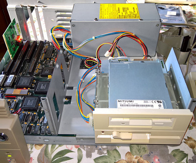
I'm trying to restore a Commodore PC40-III left in a storage for more than 10 years. I put it away because it already had this problem I had not clue.

That is what happens ~10 years ago:
The computer was working fine until the DALLAS chip failed. So I had to replace it, I put a socket in place with a new compatible DALLAS chip plugged-in the socket and then it had worked fine again.
I remember I tried different configurations to suit my needs and changed the BIOS settings, tried to add a new HDD, a 3.5" FDD. And it stopped working, with only the power LED on and the 3 keyboard lights briefly flashing.

And what happens yesterday:
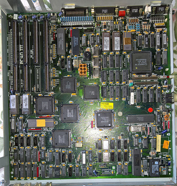
I checked the PCB, especially the capacitors, found nothing. Disassembled the PSU, checked everything. The capacitors are good and the voltage (+5, +12, -12) are near perfect. Everything in this machine look brand new. Checked for shorts from the PSU plugs on the main board. Here too, everything is good. Then:
1) I reassembled the machine and I started it without any cards or disks connected and it worked right away with only configuration normal errors during POST, and the time was only 10 minutes ahead (the DALLAS chip is still working fine). Then 2) I plug the original floppy drive, restarted the machine and reconfigured the mouse (Amiga mouse port), serial, parallel port and the floppy drive (5.25" 1,2 MB double density). The computer restarted with no error, trying to boot on the floppy as I set both HDD drive to "None" in the setup. I was really happy to see this computer miraculously alive again.
3) Having installed a 3.5" FDD at the time it first failed and wanted to use it in addition to the original FDD. I replaced the original floppy ribbon cable with another. Because the original only have two old floppy connectors. The new one has two pairs of connectors (old and new) and a twist between the two pairs for drive B & A. I know it work because I used it on a 486 machine. The original cable have no twist because the drive number is set by jumpers. So, to avoid any mistake and to proceed step by step, I didn't change the jumper settings on the original FDD and just plug it on the first port of the ribbon cable (before the twist), letting the 3.5" disconnected. That mean no changes, except having replaced the cable.
4) I started the PC, and nothing.... It stopped working again, the same way it did ~10 years ago. And impossible to start it again. The power LED is on and the keyboard lights flashing half a second just after power on.
5) I checked if chip became hot, found none.
5) I plug-in a diagnostic card. I think the machine use a Phoenix BIOS customized by Commodore, but I'm not sure as I found no information. The BIOS information is "Commodore 286 BIOS Rev. 2.01" with the low and high ram (390339-03 35C1 and 390340-03 3F3F).
6) I removed the DALLAS chip and tried to start the machine. No change. That's exactly the same.

Here is what the diagnostic card tells:
* Power lines are OK
* CLK is on
* Frame is on
* Reset is on when reset button is pressed, which lit briefly IRDY, the both goes off.
* POST stop at code 08

From the diagnostic card manual for a Phoenix BIOS:
- 08 is "BIOS Initialize chipset with initial POST values".
- 09 is "Set in post flag"
I think it is a Phoenix BIOS because the VGA chipset is a Phoenix and the peripheral interface (P8242) is also made by Phoenix but I have no proof of that and I may be wrong because it can be a BIOS totally made by commodore with its own error table.

From the manual (https://ia802308.us.archive.org/0/items/pc-40 … 90_MAR_text.pdf), I found this, but I don't know if the code there match to what the diagnostic cards display:
Test 08 (H) 0000 1000 (B)
Test 08 writes and reads the first 128K of RAM and verifies block size is 128K. First pass writes addresses into data, the second
pass writes the complement of the address into data. Memory is cleared after test. The battery status is also confirmed in test 08.
***Failure in test 08 indicates possible defective RAM or RAM logic.
Test 09 (H) 0000 1001 (B)
Test and configure video. A search is made to determine if MDA, CGA or a special video adapter is configured, if not the
onboard VGA is enabled and a call to VGA bios is executed. The dip switches are read to determine the default video mode.
NOTE: The mode register setting in the 5720 controls the reset signal to the onboard VGA controller chip. If no special video
adapters are found on the expansion bus then ‘‘NOVID’”’ from the 5720 to the PVGA is negated.
On completion of this test the title and copyright message are displayed.
Test 0A (H) 0000 1010 (B)
Test RAM from 128K to 640K. A display message is generated indicating that the base RAM of 128K, Test 08, is OK.
Blocks of 128K, starting at 128K are then tested by writing, reading and verifying RAM. The first pass writes addresses to data,
that is, the address which defines the physical location is also used as the bit pattern that is being written. The second pass writes
complement of address into data.
The test displays results in blocks of 128K to the console each time a 128K boundary is reached.
At completion of the onboard memory test the CPU is placed in virual mode and a test for virtual memory (over 1 MEG) is started.
NOTE: See test 26 (H).
***Failure in test OA indicates a defective RAM.

If the code matches, it would means there is a RAM problem. But when working, the computer always test RAM with success and is very stable when left running. So that is strange...

I'm totally lost here but what I think that it is possible it can have a problem with the CMOS. Maybe the DALLAS chip have problem to read or record information. Maybe the soldering is bad, despite visually being fine. Maybe the problem is elsewhere.

This machine is quite good as it have an onboard Paradise VGA adapter, it can switch between 6, 8 and 12 Mhz from keyboard sequence and have an embedded BIOS configuration tool. I really would like to see it working again, so I hope to find some help here.
I hope I can find some help here to debug the machine to find where the problem lies. Thank in advance.

Knowing things is great. Understanding things is better. Creating things is even better.

Reply 1 of 5, by Datadrainer

User metadata
Rank Member
Rank
Member

In case the CMOS data were corrupted I tried to clear the DS12887A by wiring the GND to RCLR bar for a few seconds. But nothing have change in the boot sequence. I still got the error code 00 08. I have redone the soldering of the socket and tested some traces, all seems fine. Originally the job was well done. I begin to think the problem is elsewhere. Each time the thing occurs after changing the configuration and having done something with the motherboard disks ports. Maybe there are bad soldering around the HDD and FDD ports. I'll check that tomorrow. I'll remove all socketed chips and clean the contacts too. Who knows.
I will try everything I can to save this pesky Commodore.

Knowing things is great. Understanding things is better. Creating things is even better.

Reply 2 of 5, by snufkin

User metadata
Rank Oldbie
Rank
Oldbie

Which Dallas chip did you use, can you clear the CMOS? I'm assuming you've tried unplugging all the drives again? Also, I'm not clear from a quick look through the service manual whether the floppy interface is IBM style (twist in cable to select drive) or Shugart style (drive select jumper on the drive). I think it might be Shugart, in which case you'll need a floppy drive that can be jumpered to fit.

Reply 3 of 5, by Datadrainer

User metadata
Rank Member
Rank
Member
snufkin wrote on 2022-02-07, 00:34:

Which Dallas chip did you use, can you clear the CMOS? I'm assuming you've tried unplugging all the drives again? Also, I'm not clear from a quick look through the service manual whether the floppy interface is IBM style (twist in cable to select drive) or Shugart style (drive select jumper on the drive). I think it might be Shugart, in which case you'll need a floppy drive that can be jumpered to fit.

The DALLAS is a DS12887A that I clear the RAM with no change unfortunately.
The floppy connector is a Shugart so it needs drives with a jumper setting which I have in the machine (5.25" and 3.5").
The floppy connector is a normal IBM PC compatible connector. I checked the Chinon 5.25" drive and indeed it has no jumper. So it means 1) I can use classic standard 3.5" FDD, even modern ones so I put a more reliable Mitsumi in place instead of the Epson. 2) The original ribbon cable is not original as it is not twisted... 3) I remembered jumpers on the 5.25" but that was surely for another machine.

Correction on the part 3) of my explanation as it was not very clear, here are the detailed steps of what I have done.

  • Tried a few start/restart with, cold and hot with no floppy drive connected with success.
  • Then started with floppy drive connected with the original cable. Entering the BIOS configuration setup, that is done after the boot sequence at any time, by pressing on the keyboard Ctrl + Alt + Esc. I configured the drive, setting no HDD (as I would like to use a XT-IDE Deluxe), enabled COM and LPT ports and adjusted the time as it was little in advance. Saved and restarted (hot reset done by the Setup). Everything was detected and the drive was seeking at boot and a message to insert a floppy to boot was displayed.
  • Then, I switched off the machine and replaced the floppy cable. And when switching it on again, it hasn't started. That is why the two suspects where the CMOS and the handling of the floppy cable.

I tested the cable since wire by wire and it is good. So the problem was not with it. Maybe with the electronic or solder near the connectors. To insert or remove HD or FDD cables bring some constraints on the board. The chassis of this machine is quite badly engineered. Amongst many things, there is little space, only a hole, for accessing the disks ports. And when the PSU block is installed (the PSU is attached to a support where the HDD and FFDs are attached too) and as there is no holder under the MB where the ports are, the nearest ones are on on each side on the keyboard connector (located on the right side of the machine) it could be a problem with damaged traces, pads or solders in the area.

A post error code 08 is at the very beginning of the POST sequence. I may be wrong... but on such machine, does stopping at 08 means it passed 08 and stopped at 09, or does it means it engaged 08 and never passed it?
That is why I also wrote the 09 post code for both Phoenix and the manual.
The MB is very big with a lot of ICs. I must be sure about the error code. Logically, if the card display a 00 08 error code and the manual say the error correspond to xxx so that should be that...
Meaning if it engaged 08 and not passed it, that is a defective RAM or RAM logic. This test is just writing a 128 KB sequence to check the RAM, no to test it, as detecting/testing the RAM is step 00 10.
If it is on 09, then it is a problem with the video card.

As I said the machine was stored as not working because of this problem. When reinstalled it 10 years latter and it worked miraculously as if nothing where wrong with it.
Something happens to make it work again, but what?
And what is the culprits of it not working again?

I'll check the soldering with the microscope near the disks ports. I'll try an ISA video card too. As step 00 09 is detecting the video card, I will see.
I still doubt there is a problem with the RAM, but if it is. I'll have to remove the chips, but I have nothing to test them... I'll put sockets for further easy replacement.
The PC have 1 MB of RAM. And that brings a question: is it possible to replace the modules by bigger one to install 4 MB (8 chip of 256Kx16) instead? If I'm correct the 80286 can address up to 16 MB but 8 MB is fine for all use case of such a machine. Or have I no choice to replace by equivalent size? I think the good answer is the last one as I don't know DIP20 chip like that with more than 256Kx4 as they have only 9 address lines.
Of course, that is only if there is a problem with the RAM. As the problem can also be with a controller (Faraday), a tantalum cap or anything else...
Thanks.

Edit 1: I cleaned up the contacts of every socket. I also checked if components became hot on the RAM area, in fact everything is on the MB is cold except the CPU that become a little warm after several minutes powered on.
Edit 2: RAM chips are 256Kx4 branded Toshiba and Hitachi on two banks.

Here are some photos:

PC40-III_general.jpg
Filename
PC40-III_general.jpg
File size
234.9 KiB
Views
387 views
File comment
PC with error code
File license
CC-BY-4.0
PC40-III_MB.jpg
Filename
PC40-III_MB.jpg
File size
349.95 KiB
Views
387 views
File comment
Motherboard
File license
CC-BY-4.0
PC40-III_RAM.jpg
Filename
PC40-III_RAM.jpg
File size
230.34 KiB
Views
387 views
File comment
RAM
File license
CC-BY-4.0

Knowing things is great. Understanding things is better. Creating things is even better.

Reply 4 of 5, by 3VILC

User metadata
Rank Newbie
Rank
Newbie

Apologies in advance digging up an old thread, but I happen to have a PC40-III with the same issue. Did the OP manage to get theirs working I wonder.
Mine is the pre Dallas version so have repaired a lot of battery damage. WAS alive, then just randomly died after I left it on while I was trying to whip up a boot disk for it. POST card also stops at 08. Have spent many hours with a scope checking everything I can in the ram area and no obviously faulty signals.
I do note U1203 on mine has been replaced with a 74S175 instead of 74LS175 and this chip seems to get quite warm compared to any other logic on the board. So I think I will obtain the correct LS version since there's already a socket there. Short of that I'm running thin on ideas

***
Edit: I discovered a POST card shows code 08h even on a booting system so is no use in these machines!
Dead RAM in bank zero solved this problem.
A corrupt CMOS RAM also stopped the system booting as it thought it had logged an illegal shutdown condition. Replacing the clock chip with a necroware one solved this for me.

Reply 5 of 5, by Datadrainer

User metadata
Rank Member
Rank
Member
3VILC wrote on 2023-10-06, 05:22:
Apologies in advance digging up an old thread, but I happen to have a PC40-III with the same issue. Did the OP manage to get the […]
Show full quote

Apologies in advance digging up an old thread, but I happen to have a PC40-III with the same issue. Did the OP manage to get theirs working I wonder.
Mine is the pre Dallas version so have repaired a lot of battery damage. WAS alive, then just randomly died after I left it on while I was trying to whip up a boot disk for it. POST card also stops at 08. Have spent many hours with a scope checking everything I can in the ram area and no obviously faulty signals.
I do note U1203 on mine has been replaced with a 74S175 instead of 74LS175 and this chip seems to get quite warm compared to any other logic on the board. So I think I will obtain the correct LS version since there's already a socket there. Short of that I'm running thin on ideas

***
Edit: I discovered a POST card shows code 08h even on a booting system so is no use in these machines!
Dead RAM in bank zero solved this problem.
A corrupt CMOS RAM also stopped the system booting as it thought it had logged an illegal shutdown condition. Replacing the clock chip with a necroware one solved this for me.

@3VILC
Sorry to reply such a long time after your reply.
Thank you very much for your feedback. I suspected it, but knowing POST is not supported is good to know and will avoid me to lose time with it.
I still not managed to fix this machine this day as I have a little time for that, unfortunately. But from a recent close inspection what I found in mine is a tantalum cap above an ISA slot is fried. But it is not shorted, and doesn't explain why the computer does start once a while, and then does not. So I suspect a problem with the CMOS, maybe the replaced DALLAS chip is bad somehow (Necroware's nwX287 can be a solution here). I tested each RAM chip with an oscilloscope and they seems all good. In fact everything I could test seems good even on the ISA slots, despite the bad cap. ? Signals with clear voltages, nothing erratic. And without a proper technical documentation, that I'm not able to find, it will be hard to fix.

Knowing things is great. Understanding things is better. Creating things is even better.