VOGONS


First post, by nuno14272

User metadata
Rank Member
Rank
Member

Hello everyone.

Just got myself a intel VS440FX socket 8 motherboard... with a pentium pro 180mhz.. I'm super excited.
Got it from a local scrap yard..
When close inspected, its missing some components.. my world just colapsed.. damm.
i've figured out thar that the IC ists a NDS9410A power relutation transisor.
But need help with the rest.

Nedd to identify what's the L8L1 , FB8L1, C9L1, Q10L3.

Attachments

  • vs440FX_2.jpg
    Filename
    vs440FX_2.jpg
    File size
    186.56 KiB
    Views
    1100 views
    File comment
    WHAT I'M MISSING
    File license
    Public domain
  • vs_440FX_2.jpg
    Filename
    vs_440FX_2.jpg
    File size
    161.26 KiB
    Views
    1106 views
    File comment
    WHAT I'M MISSING
    File license
    Public domain
  • Intel_VS440FX_F.jpg
    Filename
    Intel_VS440FX_F.jpg
    File size
    1.23 MiB
    Views
    1106 views
    File comment
    A GOOD BOARD EXAMPLE
    File license
    Public domain

1| 386DX40
2| P200mmx, Voodoo 1
3| PIII-450, Voodoo 3 3000

Reply 2 of 15, by nuno14272

User metadata
Rank Member
Rank
Member

Can you take the foto really close in each of the missing components so i can see the markings (wahts write)?

1| 386DX40
2| P200mmx, Voodoo 1
3| PIII-450, Voodoo 3 3000

Reply 3 of 15, by bofh.fromhell

User metadata
Rank Oldbie
Rank
Oldbie
nuno14272 wrote on 2022-04-04, 16:24:

Can you take the foto really close in each of the missing components so i can see the markings (wahts write)?

Should be no problems to read?
https://i.imgur.com/T6pDOcE.jpeg
Its a bit blurry, but my camera cant really get closer then this WO another lens =/

Reply 4 of 15, by pentiumspeed

User metadata
Rank l33t
Rank
l33t

That through hole solder holes are for Dell's PSU pinout using two plug connectors, not populated.

Go ahead and power up with normal ATX PSU and a video card, and a Pentium Pro processor.

Cheers,

Great Northern aka Canada.

Reply 5 of 15, by bofh.fromhell

User metadata
Rank Oldbie
Rank
Oldbie
pentiumspeed wrote on 2022-04-04, 19:42:

That through hole solder holes are for Dell's PSU pinout using two plug connectors, not populated.

Go ahead and power up with normal ATX PSU and a video card, and a Pentium Pro processor.

Cheers,

I believe he means the missing components in the first picture.
Definitely not left out by purpose =)

Reply 6 of 15, by snufkin

User metadata
Rank Oldbie
Rank
Oldbie

Not much help, but from the photo:
L8L1 : HM00-94885A This'll be an inductor of some sort, but can't find a datasheet for it, so it'll need to measured or guessed
FB8L1 : unmarked as far as I can see, a ferrite bead of some value, but again will need to be measured or guessed
C9L1 : ceramic capacitor of some value. If you can work out where each side goes then you might be able to work out what the voltage rating is.
Q10L3 : SOT23 package with what looks like 2X marking, which according to this http://www.marsport.org.uk/smd/mainframe.htm is a SOT23 2N4401
NPN transistor: https://www.mouser.com/datasheet/2/149/MMBT4401-889780.pdf

Reply 7 of 15, by pentiumspeed

User metadata
Rank l33t
Rank
l33t

Oooh. That's very interesting. Best thing is get another Intel board as these parts are not easily sourced to look correct.

Also the capacitor is incorrect, use quality low ESR instead.

Cheers,

Great Northern aka Canada.

Reply 8 of 15, by snufkin

User metadata
Rank Oldbie
Rank
Oldbie
snufkin wrote on 2022-04-04, 21:01:
Not much help, but from the photo: L8L1 : HM00-94885A This'll be an inductor of some sort, but can't find a datasheet for it, so […]
Show full quote

Not much help, but from the photo:
L8L1 : HM00-94885A This'll be an inductor of some sort, but can't find a datasheet for it, so it'll need to measured or guessed
FB8L1 : unmarked as far as I can see, a ferrite bead of some value, but again will need to be measured or guessed
C9L1 : ceramic capacitor of some value. If you can work out where each side goes then you might be able to work out what the voltage rating is.
Q10L3 : SOT23 package with what looks like 2X marking, which according to this http://www.marsport.org.uk/smd/mainframe.htm is a SOT23 2N4401
NPN transistor: https://www.mouser.com/datasheet/2/149/MMBT4401-889780.pdf

Was just thinking a bit about this, and obviously it'll be better if you can get actual measurements of what the parts are, and also to check what bits of the board this supply is powering so you know what's at risk, but if you're interested in guesses:
FB8L1 : looks to be about 9mm x 4mm
https://www.mouser.co.uk/ProductDetail/Laird- … DWF%2FH1Q%3D%3D
page 28 here: https://www.mouser.co.uk/datasheet/2/987/Lair … and-1947796.pdf
Mouser say it's 8.5mm x 3.1mm, the datasheet says 8.5mm x 4.5mm. So it should fit. Max current 10A, which sounds reasonable.

C9L1 : case size might be imperial 1206/metric 3216 and I'm going to guess it should be around 10uF (not decoupling, not bulk, but probably not part of a clever analogue timing circuit) and electrolytics nearby are rated at 25V so maybe best to use a 25V part here as well.
But maybe better to measure the capacitance of the nearby C9M7 that you still have on your board.

Q10L3 : There are a bunch of MMBT4401 types here: https://www.mouser.co.uk/c/semiconductors/dis … 20case=SOT-23-3
Although some are only 100mA collector current rated, so you may want to select the 600mA ones to be on the safer side, and higher power dissipation is probably also good.

L8L1 : probably the most important one to get right, and the least likely to get right. Looks to be around 7.5mm square.
Mayyyybe something like this https://www.mouser.co.uk/ProductDetail/Sumida … Wyx2rA5vg%3D%3D 1.2uH, 15A, 6.7mOhm. Pads look like they'll make contact.

A lot of guesses there, so not very safe. Might be fun. If you do try then you'll want an oscilloscope to check how much ripple there in on the supply.

Reply 9 of 15, by nuno14272

User metadata
Rank Member
Rank
Member

I see you pointing that the FBl1 is a ferrite bed. Males sense..but...

Why the polar settings? Ferrite are supressors.. always beelived that was no polarity involved.. and in the board is a + and a -

1| 386DX40
2| P200mmx, Voodoo 1
3| PIII-450, Voodoo 3 3000

Reply 11 of 15, by Horun

User metadata
Rank l33t++
Rank
l33t++

My opinion only: there is a reason those parts were removed w/o damaging any other parts. Best guess is the board is dead and those parts were "donor" parts for another similar board.
Sorry if that is bad news but those parts were 'surgically' removed and not broken off by bad handling. Replacing them probably will not get the board working but never know.... just my opinion

Hate posting a reply and then have to edit it because it made no sense 😁 First computer was an IBM 3270 workstation with CGA monitor. Stuff: https://archive.org/details/@horun

Reply 12 of 15, by luckybob

User metadata
Rank l33t
Rank
l33t

there's plenty of damage, those parts were ripped off somehow.

that long black part, is a diode, not a bead.

I should have one of these boards, I'll see if I can find it tomorrow.

It is a mistake to think you can solve any major problems just with potatoes.

Reply 13 of 15, by snufkin

User metadata
Rank Oldbie
Rank
Oldbie

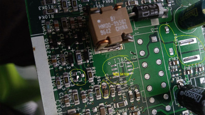
Yeah, you can see the damage and some solder rework on the big inductor L9L1, and half of C9L1 is still on the board, plus there's some other rework been done with surface mount capacitor C8M1 being replaced with a through-hole. Given the amount of damaged components I'm surprised at how little damage there seems to be on the PCB. I think there's a fair chance there may be more wrong with the board.

PIcking up on Pentiumspeed's point, I noticed that the replaced capacitor is a Chongx, who don't have a particularly good reputation, e.g.: https://www.eevblog.com/forum/projects/beware … ngx-capacitors/

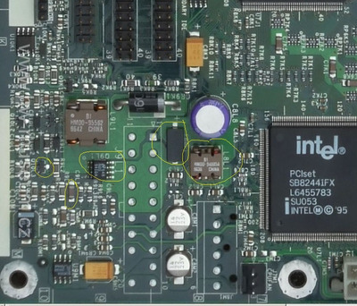
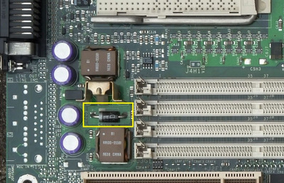
I went with ferrite bead for my guess for a couple of reasons. Firstly, I don't think I've ever seen a diode that doesn't have some sort of case marking for polarity, and I can't see even a faint one on that component in bofh's photos. Other diodes on the board have one end marked with a grey stripe. Secondly, the silkscreen marking for it is FB, and other diodes on the board are designated CR (current rectifier?). If you look over by the PS/2 port there are a bunch of unpolarised components where you'd expect to see some ferrite beads and the silkscreen has them as FB.

OTOH, it seems an odd place to have a ferrite and it's not completely unknown for silkscreen to have mistakes. If luckybob can check the components on an actual board then that's far better than random guessing on my part.

Reply 14 of 15, by nuno14272

User metadata
Rank Member
Rank
Member

The board was taken from a scrap yard. so the damage is only in this zone and because they have put a case on top of this board... and the corner or the case ripped out this 4 or 5 conponentes...
The only thing i did, so far, was exchange the aluminium eletrolitic capacitors with new ones.. (and used apparently a bad brand - they where 25V original...used 100V.. so i think i'm ok...🤣)...

Yes the board as other ferrite beds near the rear connectors.. not this big.. but unpolarised.. .

The marking + being for the other diode next to it doesn't seens right because the black list is the -... i've always seens the silkscreens on other board with FB being ferrites but this board is making me second thoughts..

WAIT... JUST WAIT

in this foto.. the diode as the +.. is the + for the diode after all ?????? man...

Attachments

  • skt8_1.jpg
    Filename
    skt8_1.jpg
    File size
    196.31 KiB
    Views
    806 views
    File comment
    HMMM..
    File license
    Public domain

1| 386DX40
2| P200mmx, Voodoo 1
3| PIII-450, Voodoo 3 3000

Reply 15 of 15, by nuno14272

User metadata
Rank Member
Rank
Member
luckybob wrote on 2022-04-07, 05:11:

there's plenty of damage, those parts were ripped off somehow.

that long black part, is a diode, not a bead.

I should have one of these boards, I'll see if I can find it tomorrow.

I there.. digging out this thread..

i think is time to try out this board.. I've ordered some parts from portuguese icshop mauser.pt, but..
i think luckybob as pointed to something right.. a simple ferrite bead in that place one the board does make sense ?

1| 386DX40
2| P200mmx, Voodoo 1
3| PIII-450, Voodoo 3 3000