VOGONS


First post, by dekkit

User metadata
Rank Member
Rank
Member

Updated - with links to mapped out Information (last updated 22/04/2023)
This turned into quite a project that began around April 2022. While this has been quite a learning curve, I intended to update this first post in case anyone finds this via google and would like to know more information about this SBC and turn it back into a usable 486 system.

KEY SECTIONS - Index
VIDEO - VGA Socket
Link to VIDEO DRIVERS
KEYBOARD - PS/2 Keyboard socket
HDD IDE sockets (CF Card Adapter)
CF Card Recommendations
SERIAL PORTS socket + RESET Button pins
PS/2 MOUSE to SERIAL MOUSE - DIY using Ardunino Nano
PARALLEL PORT Socket
FLOPPY DRIVE Socket
CMOS BATTERY - DIY Adapter (3v coin holder)
PC104 Socket and link to PC104 to ISA - DIY Adapter
PC104 Network Card Add on
BIOS - Original Video (32KB)
BIOS - Original System BIOS (128KB)
BIOS - Modified System BIOS for CRT mode (128KB)
Using a 12v PSU - ATX Breakout board and PICO PSU
Near Finished - Perspex Case + Plastic Stand-offs + Power Buttons
...and lastly
VIDEO DRIVERS & BIOS BACKUP PACKAGE

Background - Original Post

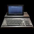
A few months ago I acquired the following neatly sized 486dx2-80 and SBC motherboard off a local market place advert but unfortunately couldn't find much user information at all on it online.

I have slowly been going through studying the ICs - ie reading through 'Chips' datasheets for pin outs and application examples, then using a multi-meter to trace key chip pins . Also comparing it to other service docs for SBC, 486 chips, socket 3 mainboards of similar era etc to help speed the process.

While its been fun journey mapping out something made 27 years ago for an eventual dos mini rig, I'm keen to see if anyone else has see one before and/ or have any docs in their inventory that could help verify?

Single Board Computer (SBC) - 486-DX2-80 - Innovative Technologies, Houston, Texas - 1995

Mainboard.png
Filename
Mainboard.png
File size
379.44 KiB
Views
2296 views
File license
CC-BY-4.0

It also came with PC104 socket and a custom PC104 network card + IDC socket (which looks to map through a few sockets into a single interface)

Mainboard_Network.png
Filename
Mainboard_Network.png
File size
1.27 MiB
Views
2296 views
File license
CC-BY-4.0

On the back of the pcb, it has the following markings

(C) 1995
Innovative technologies
Houston, Texas
it / 486
REV C
SN: C-004-xxx-1-0

I found someone asking the same question here (with no real answer either) dated Oct 5, 2016 (https://forums.overclockers.com.au/threads/wh … -board.1206509/)

If no one has any documentation that can help, i'll continue to map out the ports from the datasheets and post my progress and results here (hopefully i can still continue to edit the first post)

dekkit

Last edited by dekkit on 2023-04-22, 14:22. Edited 15 times in total.

Reply 1 of 66, by dekkit

User metadata
Rank Member
Rank
Member

VGA pin out - CHIPS F65548 - FlatPanel VGA Controller
From reading through various SBC docs, many of these era industrial SBC were designed to be able to be used with either digital LCD panels or VGA monitors.

Scanning the PCB, i noticed a large IC that I suspected might be part of the video circuitry and found a similar enough datasheet (F65540/F65545 with similar pin layouts) to start probing the pins - to see if i could try and hook in a VGA socket.

Location

VGA_Location.png
Filename
VGA_Location.png
File size
379.79 KiB
Views
2281 views
File license
CC-BY-4.0

CHIPS F65548

VGA_CHIPS_F65548.png
Filename
VGA_CHIPS_F65548.png
File size
939.77 KiB
Views
2281 views
File license
CC-BY-4.0

Datasheet Examples
Relevant Pins: 65= Hsync, 64 =VSync, 60=RED, 58=GREEN, 57=BLUE,56=AGND

VGA_CHIPS_F65548_datasheet1.png
Filename
VGA_CHIPS_F65548_datasheet1.png
File size
47.81 KiB
Views
2281 views
File license
CC-BY-4.0

Relevant Application Example
What was useful in the application examples was the location of the ferrite beads (denoted by 'FB' in the schematic). As the ferrite beads were on the same side as the chip (the resistors and capacitors were on the back of the PCB)

VGA_CHIPS_F65548_datasheet2.png
Filename
VGA_CHIPS_F65548_datasheet2.png
File size
36.15 KiB
Views
2281 views
File license
CC-BY-4.0

Then it was a case of carefully mapping the F65548 IC pins to the relevant IDC socket pins using multi-meter to test for continuity between section of the motherboard and a bit of luck.

Pinout
See label HDR24

VGA_RGBHV_IDC_Pins.png
Filename
VGA_RGBHV_IDC_Pins.png
File size
441.71 KiB
Views
2281 views
File license
CC-BY-4.0

Note - the VGA pinout was sourced from wikipedia here: https://en.wikipedia.org/wiki/VGA_connector#E … ectrical_design

And finally to build a cable to verify and some initial success...

Last edited by dekkit on 2023-04-22, 12:19. Edited 1 time in total.

Reply 2 of 66, by dekkit

User metadata
Rank Member
Rank
Member

Video Output Test
Good to see it boots and the ram on passed the initial test (32MB will plenty for this), the CMOS battery was clearly dead, but a little disappointed that it was only registering 66Mhz (but hopeful i can benchmark this properly at some point).
For power, I threw together pico psu in a project box and wire up +12v, -12v, +5v, GND to an old PC molex cable.

Cable wiring example

VGA_RGBHV_CableTest.png
Filename
VGA_RGBHV_CableTest.png
File size
920.39 KiB
Views
2274 views
File license
CC-BY-4.0

Output

VGA_RGBHV_Videotest.png
Filename
VGA_RGBHV_Videotest.png
File size
108.35 KiB
Views
2274 views
File license
CC-BY-4.0

Still a bit to go, but initial signs are looking good.

Reply 3 of 66, by dekkit

User metadata
Rank Member
Rank
Member

PS/2 Keyboard Pin out - CHIPS F84041

After getting VGA out, was keen to access the BIOS and see what options were available. Given that this era computing typically had PS/2 keyboard and mouse sockets on the board, i went looking the Chips IC mostly likely to control the keyboard and mouse. Then looked for which pins were nearby and checked traces.

Based on an earlier project, PS/2 mouse and keyboard typically use VCC (to power the IC within the device), Ground (return), Data (to communicate), Clock (for timing of data communication) - so these were the pins on the IC i was looking for.

Location

Keyboard_IC_Location.png
Filename
Keyboard_IC_Location.png
File size
379.69 KiB
Views
2203 views
File license
CC-BY-4.0

CHIPS F84041

F84041_IC_KB_MOUSE_Pins.png
Filename
F84041_IC_KB_MOUSE_Pins.png
File size
59.97 KiB
Views
2203 views
File license
CC-BY-4.0

Keyboard and Mouse Socket Locations

Keyboard_Mouse_Sockets.png
Filename
Keyboard_Mouse_Sockets.png
File size
380.52 KiB
Views
2203 views
File license
CC-BY-4.0

Compared to typical motherboard connectors, these PS/2 sockets were only 4 pins and as a result couldn't find anything online - so went down the path of creating another another custom cable.

Pinout - PS/2 Keyboard

Keyboard_pinout.png
Filename
Keyboard_pinout.png
File size
320.19 KiB
Views
2203 views
File license
CC-BY-4.0

Left to right
- VCC
- Data
- Clock
- Ground

I suspect the mouse pin will be aligned exactly the same way (but not yet tested) and will update this post when confirmed.

Note - PS/2 socket pins easily found on wikipedia https://en.wikipedia.org/wiki/PS/2_port

Success

Keyboard_success1.png
Filename
Keyboard_success1.png
File size
1.46 MiB
Views
2203 views
File license
CC-BY-4.0

So now its usable, I can check out the bios and interface with the SBC. I was hoping to be able adjust the clock-speed within the bios as the system indicates its running at 66Mhz where as the chip support 80Mhz, but looks like this can only done with the jumper grid near the CPU (which is very risky without documentation).

Next we can hopefully add an IDE disk....

Reply 4 of 66, by dekkit

User metadata
Rank Member
Rank
Member

IDE Socket - 44pin and also 40pin - F82C735
While there were only few likely contenders, I decided to search for which IC controls the IDE ports - particularly as i wasn't sure what that other 40 pin was for. The CHIPS F82C735 controller handles not only the IDE port but printer port, com ports, and floppy disk drive ports.

Location

F82C735_IC_Location.png
Filename
F82C735_IC_Location.png
File size
379.7 KiB
Views
2191 views
File license
CC-BY-4.0

CHIPS F82C735

F82C735_IC_IDE_Pins.png
Filename
F82C735_IC_IDE_Pins.png
File size
50.35 KiB
Views
2191 views
File license
CC-BY-4.0

IDE Socket Location - 44 pin and 40 pin
Updated (22/04/2023 - added socket labels - Note these are marked with the labels HDR37 (44 pin) and HDR36 (40 pin) )

44_IDE_40_IDE_Port_Location.png
Filename
44_IDE_40_IDE_Port_Location.png
File size
380.55 KiB
Views
2191 views
File license
CC-BY-4.0

Pinout - IDE 44 pin and IDE 40 pin

40pin_44pin_IDE_Ports.png
Filename
40pin_44pin_IDE_Ports.png
File size
366.78 KiB
Views
2191 views
File license
CC-BY-4.0

Most of the 44pin and 40 pin ide pins were directly connected to each other (except for the extra vcc and ground pins on the 44 pin socket). I suspect there is a maximum of 2 x IDE drives possible, but i did notice the option for 4 x IDE in the BIOS, so may need to explore this further at a later point.

Note - IDE socket pins also found on wikipedia here https://en.wikipedia.org/wiki/Parallel_ATA

Outcome

IDE_CF_Card_Adapter.png
Filename
IDE_CF_Card_Adapter.png
File size
337.96 KiB
Views
2191 views
File license
CC-BY-4.0

On the IDE 44p pin socket, I wired in a few IDE to CF adapters and successfully boot into MS DOS, and of course ensured that DOOM works.

Warning!! - rechecking the cf card picture above - I noticed the card adapter is the wrong way around on the 44pin caable (it should be flipped upside down)

Next steps...to document the printer and floppy ports. Also an pc104 addon card that it I suspect is network card.

Last edited by dekkit on 2023-04-22, 12:08. Edited 2 times in total.

Reply 5 of 66, by dekkit

User metadata
Rank Member
Rank
Member

Doom Test
Obligatory 'did it run' doom? Yes, performance was smooth and very playable, but admittedly didn't check for frames etc. Keen to put a sound card in this at some future point.

44_IDE_TEST_DOOM.jpg
Filename
44_IDE_TEST_DOOM.jpg
File size
940.1 KiB
Views
2186 views
File license
CC-BY-4.0

Reply 6 of 66, by dekkit

User metadata
Rank Member
Rank
Member

Updated (22/04/2023)- PC104 Socket Location
Add pic of the PC104 socket location, which are pin compatible with ISA cards.

Mainboard - PC104 Location.png
Filename
Mainboard - PC104 Location.png
File size
378.98 KiB
Views
1160 views
File license
CC-BY-4.0

Original post...

A bit of a progress update:

While mapping out the floppy port and printer port, i decided not to bother adding the cables at this point (ill provide a pic of where the sockets are later) - I figured cf cards would be enough for my needs.

Instead I decided to make rasteri's PC104 to ISA adapter and see if I can get a soundcard connected.

Really useful hardware that can be DIY assembled. For more info see Cheap Homebrew ISA->PC104 adapters

As a result managed to add soundblaster support via a very decent clone (ESS 1868f)

20220521_163505_2.jpg
Filename
20220521_163505_2.jpg
File size
503.56 KiB
Views
2036 views
File license
CC-BY-4.0

Very happy with the audio quality.

Last edited by dekkit on 2023-04-22, 11:34. Edited 2 times in total.

Reply 7 of 66, by dekkit

User metadata
Rank Member
Rank
Member

Updated (22/04/2023) - Serial / COM ports + Reset Pins
Updated to include pics of the location of the 2 x COM ports, plus also the reset button pins. The COM ports were later used to connect a serial mouse (and eventually a PS/2 to serial converter)
HDR36= Reset pins
HDR13= COM
HDR14= COM

Serial - COM Ports RESET pins.png
Filename
Serial - COM Ports RESET pins.png
File size
380.45 KiB
Views
1157 views
File license
CC-BY-4.0

Original Post...

Unfortunately, ive been unable to get the PS/2 mouse port working despite efforts to date.

The most likely pins are correctly mapped to the relevant pins on the chip, and despite wiring a custom cable - was not able to get a ps/2 mouse to communicate at all.

There may be a jumper somewhere to enable or disable a ps/2 mouse but nothing stood out for this purpose. Nothing in the bios either.

If one reading this has any suggestions or identifies anything I missed (ie a jumper or a set of pins that may enable it) - please reply to this as I'm keen to get it working.

As a fall back, I managed to wire in a COM port (Serial) and test out a serial mouse - which was successfully recognised by MOUSE.COM

The mainboard has 2x Serial COM Ports
With an additional x1 also provided by the custom.network addon pc104 card (so 3 all up)

NOTE - there are actually 2 x standards for wiring COM Ports to a mainboard header:
"AT/Everex"
Vs "DTK/Intel"

This mainboard and pc104 network card both used the DTK/Intel header standard - HOWEVER the com port to idc cable from ali express was mapped to " AT/Everex" standard- so I needed to remap the cable (using dupont cables)

Here is a great link explaining the two
http://www.bodenzord.com/archives/117
Including the pin outs for both (useful in case you need to figure out why your com ports arent working propely).

UPDATE - in case the link goes down it's a super useful reference worth preserving here (with all thanks to the original author).

Screenshot_20230212-211812(1).png
Filename
Screenshot_20230212-211812(1).png
File size
110.5 KiB
Views
1534 views
File license
Fair use/fair dealing exception

At this stage in plannig to build a ps/2 to serial mouse converter (using an arduino) as a work around but it would be neater if I could just use the inbuilt one (if I can get it working)

20220929_201817~2.jpg
Filename
20220929_201817~2.jpg
File size
1004.86 KiB
Views
2027 views
File license
CC-BY-4.0
Last edited by dekkit on 2023-04-22, 12:16. Edited 3 times in total.

Reply 8 of 66, by dekkit

User metadata
Rank Member
Rank
Member

Have now completed a ps/2 mouse work around using Lameguy64's excellent Lame Mouse Converter - this handy device sits inbetween my Ps/2 mouse socket and a spare serial com port and does all the required signal conversions.

Link: https://github.com/Lameguy64/LameMouseConverter

For this addon, I used an Arduino Nano and a cheap Max232 to DB9 (TTL to RS232) (found on aliexpress/ebay etc).

The arduino was fairly easily programmed (once the I got around an issue with arduino IDE) and I modded the cheap Max232 to Db9 to follow the LameMouseConverter schematic (fyi use the free open Kicad app if you have difficulty viewing it). This added the RTS lines and I connected a few pins of the serial port (which means I can communicate with it via dos echo commands).

received_445440534395834.jpeg
Filename
received_445440534395834.jpeg
File size
234.86 KiB
Views
1980 views
File license
CC-BY-4.0

Tested with two Microsoft mice and it worked brilliantly each time. The arduino leds flicker each time it detects movement in the mouse or a button press.

Note: The arduino and Max232 are powered from the 5v rail from the pico supply.

Tested with a few games and really happy with the responsiveness of it.

The original World of Warcraft was a good test game.

20221023_230519~2.jpg
Filename
20221023_230519~2.jpg
File size
817.88 KiB
Views
1980 views
File license
CC-BY-4.0

Also tested cannon fodder which was decent too.

Reply 9 of 66, by rasz_pl

User metadata
Rank l33t
Rank
l33t

You arent the only one with CHIPS F84041 mouse problems
https://tinkerfiddle.blogspot.com/2018/07/hp- … -ps2-mouse.html
https://tinkerfiddle.blogspot.com/2018/07/hp- … ng-my-shot.html
>But Other Than that, How Did the PS/2 Work, Mrs. Lincoln?
>No. Not sure why. The mouse definitely works, and Windows 95 has detected the PS/2 hardware, but it doesn't register the mouse. I'll put a scope on it later.

sadly no more posts about the mouse

Open Source AT&T Globalyst/NCR/FIC 486-GAC-2 proprietary Cache Module reproduction

Reply 10 of 66, by weedeewee

User metadata
Rank l33t
Rank
l33t

interrupt 12 somehow not enabled ?

Right to repair is fundamental. You own it, you're allowed to fix it.
How To Ask Questions The Smart Way
Do not ask Why !
https://www.vogonswiki.com/index.php/Serial_port

Reply 11 of 66, by dekkit

User metadata
Rank Member
Rank
Member

My current theories on the ps/2 mouse port not working:
- is there is either a bios /eeprom value that was never set (I can see via Google image search that slightly newer bios menus added it as an item that can be enabled/disabled like com ports etc) and reading the datasheets suggest that a value can be set in the eeprom to set a mode enabling the mouse clock and data pins. But there is nothing in this bios menu that even hints at it.
- interrupt 12 line needs to be enabled via a jumper pin or bridging an empty resistor pad. The trouble was, when I traced the interrupt 12 lines - nothing connected or mapped to any of the free pins on the pcb (unless I missed something obvious)

Whats annoying is that the custom pc104 card that came with the pcb has a label that identifies which idc pins are for the ps/2 mouse. So there must be a way - would be great if I had the manual 😉

That said im very content with the mouse converter so next step is to get the Ethernet port talking in dos.

Reply 12 of 66, by rasz_pl

User metadata
Rank l33t
Rank
l33t

https://www.datasheetarchive.com/pdf/download … e=P&term=F84041

>When the internal mouse controller is being used, the IRQ12 pin is driven by the 4045 as an output, as well as feeding back into the interrupt controller logic in the 4045.

IRQ12 is handled internally

-----------------------------------
5.15.1. Host CPU Commands
The 4041 internal keyboard/mouse controller supports the host CPU commands listed below.
A7h Disable Mouse
A8h Enable Mouse

(A7h) Disable Mouse. This host command sets bit 5 in the Command Byte, causing the mouse clock to be driven
continuously low to disable the mouse interface.
(A8h) Enable Mouse. This host command clears bit 5 in the Command Byte, allowing the mouse clock to return to
the high state and be pulsed by the mouse if the mouse has new data to transmit.

>39 Soft Reset & GATEA20. Default = 04h. Typical setting = BFh for internal keyboard/mouse
controller, or B2h or 02h for external controller.
0 Mouse Interrupt enable on the control link
0 Disabled (mouse interrupt not sent to 4045)
1 Enabled (send mouse interrupt notification to 4045)
1 LIN pin function.
0 Test Function (default).
1 Link input (normal operation).
This bit should be set to 1 before enabling 4045 LOUT (Index 09h bit 4). Also, the 4041 LIN pin
should have a pull-up resistor to keep it high during and immediately following reset. If 4041
Test Mode is desired (for hardware testing), the 4041 LIN pin may be externally pulsed low while
bit 1 in this register is 0.
2 Enable Internal 8042.
0 Disabled. Keyboard pins are GATEA20 and KBRESET#.
1 Internal 8042 enabled. Keyboard pins are KBCLK and KBDATA.
3 Enable Mouse port
0 Disabled.
1 Internal 8042 mouse port enabled. Bit 2 must also be set.

22 Configuration register Address Port.
Write only port which holds the address of the Chips and Technologies Index register to be accessed
through I/O port 23. This register must be written before each access to port 23, even if the same
index register is being accessed twice in a row.
23 Configuration register data.
Accessing this port accesses the Configuration register pointed to by port 22. A second access to port
23 without writing port 22 in between will be ignored. Unless otherwise noted in the register
descriptions, reserved or undefined index registers should not be written to, and reserved bits within a
defined index register should be written as zero (or written with the same value previously read).
-----------------------------------

First thing I would do is measure voltage on Mouse Clock pin, if its low then mouse is definitely disabled in softwera

run DEBUG.exe
o 22 39
i 23

this should show us current value of register 39

run DEBUG.exe
o 64 A8
will execute "A8h Enable Mouse"

Open Source AT&T Globalyst/NCR/FIC 486-GAC-2 proprietary Cache Module reproduction

Reply 13 of 66, by dekkit

User metadata
Rank Member
Rank
Member

Thank you this is promising - will report back once I get a chance to fire it up and test.

Assuming debug.exe is it a part of dos 6.22 as ive never actually needed to use it before (also whats the risk of borking the system by messing with it?)

Reply 14 of 66, by dekkit

User metadata
Rank Member
Rank
Member

Ok update on measuring mouse pins:
Clock = 4.6v (approx)
Data = 4.6v (approx)

Found debug.exe in my fdos folder and queried as above:

output suggests internal keyboard and mouse ok from what I can read from your notes above.

I must be doing something incorrectly from a wiring or connection perspective - will have to revist my connections to rule out and be sure.

20221026_235152~2.jpg
Filename
20221026_235152~2.jpg
File size
275.12 KiB
Views
1846 views
File license
CC-BY-4.0

(Btw thanks for info above, learning more about debug.exe behind the scenes )

Last edited by dekkit on 2022-10-26, 22:05. Edited 1 time in total.

Reply 15 of 66, by rasz_pl

User metadata
Rank l33t
Rank
l33t
dekkit wrote on 2022-10-26, 13:28:

Ok update on measuring mouse pins:
Clock = 4.6v (approx)
Data = 4.6v (approx)

thats not good, because its good 😀 means mouse is not forcefully disabled (pulled low). Can you trace PS2 mouse pins to
MDATA 102 I/O Mouse data to internal 8042.
MCLK 101 I/O Mouse clock to internal 8042.
? I dont know if it still requires external transistors/inverters between

and have you still tried "o 64 A8" too?

more stuff to poke around:

>0C Port 92 and RTC feature control. Typical setting = 00h for external 8042, 30h for 4041
internal KBC.

o 22 0c
i 23

>(20h) Read Command Byte. The Command Byte is placed into the Controller Output Buffer for reading by the host
CPU. For bit definitions, see 60h command below. (The "Command Byte" is an internal byte separate from the host
CPU commands written to port 64h.)

>(60h) Write Command Byte. The next byte written to port 60h is placed into the Command Byte. On reset, the byte
is set to 70h. Scan code conversion is always enabled. Bit definitions:
7 Reserved, write as 0.
6 Reserved
5 Disable Mouse
4 Disable Keyboard
3 Inhibit Override (ignore KBINH# input)
2 System Flag
1 Enable Mouse Interrupt
0 Enable Keyboard Interrupt

I think
o 64 20
- 60
should read command Byte, will tell us if interrupt is enabled

You can try putting Oscilloscope on MDATA/MCLK and:
>(D4h) Transmit to Mouse. The next data byte written to port 60h is transmitted to the mouse. The execution time of
this command depends on mouse timing.

o 64 D4
0 60 55

dekkit wrote on 2022-10-26, 13:28:

(Btw thanks for info above, learning more about debug.exe behind the scenes )

me too 😀 I finally had to research how to do direct IO with debug without writing little programs.

Open Source AT&T Globalyst/NCR/FIC 486-GAC-2 proprietary Cache Module reproduction

Reply 16 of 66, by dekkit

User metadata
Rank Member
Rank
Member

ok will need to give this some more attention over the coming week when I can concentrate and go through this carefully.

I feel this is so close to resolving (really appreciate the extra info/clues).

Before amending any values, I'll try and output each of the current values - as im nervous about inadvertently disabling the keyboard 😀

Particularly keen to see if the correct irq is currently set to disabled for the mouse... stay tuned

Reply 17 of 66, by Sphere478

User metadata
Rank l33t++
Rank
l33t++

http://www.alexandrugroza.ro/microelectronics/index.html

If this hasn’t been posted, you’ll find this of interest. They are on the forum btw:

ALEKS

Sphere's PCB projects.
-
Sphere’s socket 5/7 cpu collection.
-
SUCCESSFUL K6-2+ to K6-3+ Full Cache Enable Mod
-
Tyan S1564S to S1564D single to dual processor conversion (also s1563 and s1562)

Reply 19 of 66, by Sphere478

User metadata
Rank l33t++
Rank
l33t++

No prob 😀

Sphere's PCB projects.
-
Sphere’s socket 5/7 cpu collection.
-
SUCCESSFUL K6-2+ to K6-3+ Full Cache Enable Mod
-
Tyan S1564S to S1564D single to dual processor conversion (also s1563 and s1562)