VOGONS


First post, by EnergyStar

User metadata
Rank Newbie
Rank
Newbie

Motherboard started with "keyboard error" and "CMOS checksum error" errors. The keyboard didn't work. Not every time the motherboard started, sometimes it crashed with the C7 error code.

- I changed electrolytes
- I checked the keyboard socket, corrected the solder
- I replaced four SMD capacitors next to the keyboard DIN connector
- I was programming the BIOS on three different CMOS chips.
- I changed the processor
- I tried on different RAM chips in different slots.

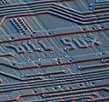
I had some brand new Dallas DS12C887 + chips, so I decided to replace it. The board stopped working on the new chip, moreover I found information that the new chip should be activated with a simple program, so I re-soldered the old chip. After this treatment, the motherboard has not started even once, it stops at the C7 error.

I put flux and fresh tin on the lower chipset - no effect. I did the same with a few other smaller chips. I tried to push them down. I desoldered and re-soldered the UMC 8667 chip that supplies voltage to the COM ports. Tried reprogramming the BIOS on different chips.

Most of the integrated circuits are cool, the CPU gets slightly hotter locally.

What else could I do?

IMG-20220503-025152.jpg

Last edited by EnergyStar on 2022-05-25, 18:33. Edited 1 time in total.

Reply 1 of 27, by majestyk

User metadata
Rank Oldbie
Rank
Oldbie

It´s a Shuttle HOT433 btw.
There still seems to be corrosion at / around the KB-connector. I would check the traces and vias in this area carefully for conductivity.
I hope you provided a socket for the Dallas RTC before replacing it several times...

Reply 2 of 27, by EnergyStar

User metadata
Rank Newbie
Rank
Newbie

I desoldered the DIN keyboard connector, cleaned it, checked the tracks and surrounding elements - no effect.

I have read this topic

Socket 5 - Dallas RTC replacement gone bad

Here is the quote I followed:

The two failing devices (Keyboard, RTC) are connected on the "X-Bus". That's an 8-bit data bus interconnected to the ISA bus via a buffer chip, usually a 74F245, as this is the chip type recommended by Intel. An interesting test might be booting with an ISA graphics card to check whether the ISA bus already behaves strangely (garbled screen or beeps), or the problem seems limited to the X-Bus.

As I suppose you only soldered near the RTC, it's unlikely that you damaged the KBCS# trace thats selecting the keyboard controller, but some signal that connects to both the KBC and the RTC, and this is the 8 data lines. So, the first thing I would check if KBC and RTC start failing at the same time is accidental shorts between the data pins D0-D7 on the X-Bus. There is a catch with the theory that shorted data lines on the X-Bus are causing the problem: The BIOS chip usually is also connected to the X-Bus data lines, but the BIOS chip obviously works fine. The board layout makes it unlikely that data lines at the KBC are working, but are non-functional at the BIOS chip.

I noticed that I have vertical stripes on the screen. They appear on both the ISA and PCI buses, but are denser for PCI. I tried on three different graphics cards. I located a similar 74F244 chip close to the CPU and replaced it - no improvement.

The cause of the problems with the start were the shortened and broken paths that suffered during desoldering of the Dallas chip. I soldered the socket, repaired all paths. On the old Dallas chip, motherboard returned to its original state displaying various error messages, problems with KB/Inteface error, FDC problem, cache damaged, cmos checksum..

After inserting the second, new (hopefully) Dallas chip, all the errors disappeared except for one:

IMG-20220525-201221.jpg

I tried to leave the motherboard on for a while to let it recharge a little, but the error persists.

Here's a comparison of the two chips - looks original, has a slightly different font. The one above is old

IMG-20220525-202236.jpg

Assuming it's brand new, is this behavior typical? Does it mean that I have to turn on the clock, which is turned off by default ? If so, how can I do this?

Reply 4 of 27, by EnergyStar

User metadata
Rank Newbie
Rank
Newbie

Datecode is 2016

So I have had to replace this chip in the past and both are from the same order. On both chips, the motherboard sometimes stops at POST code C6. After swapping, he gets up. However, it is clearly visible that on the first dallas chip more errors pop up, on the second only the "CMOS battery state low" error.

On the first chip, before errors appear, it hangs for a long time on the word "WAIT ...", after pressing F1 it sometimes continues to the next screen where it displays the error reading from the floppy disk drive. You can enter the BIOS settings, but it doesn't keep the settings.

On the second chip, after pressing F1, the BIOS loads. After setting the time and saving the settings, it reboots with the same error and does not pass to the next screen where boot should occur. Doesn't keep the settings.

For lack of ideas, I put a fresh tin on the top chipset and the UM8002 above it - no changes.

Let me repeat the question: does the new Dallas chip need to be activated, or does it happen automatically after the chip is mounted on the motherboard?

I also think that I will give the entire motherboard a bath in isopropanol, clean it, look under the magnifying glass and if I find nothing, I will start applying fresh tin on the remaining integrated circuits and all elements.

There is also the question of vertical stripes on the screen.

Reply 5 of 27, by Plasma

User metadata
Rank Member
Rank
Member

The battery is dead. Why replace a dallas with another stock dallas? Even if the battery was good it's just going to be dead again in a few years. Either do the external battery mod or use a better replacement.

Reply 6 of 27, by majestyk

User metadata
Rank Oldbie
Rank
Oldbie

You do not have to activate the Dallas RTCs manually.

Do you have the vertical stripes issue all the time or has it been gone by now?
I assume you are operating the board without cache and TAG chips because they fail quite often and can produce all kinds of errors.
Also you should try to freeze the chipset ICs with coolant spray before turning the board on to see if this makes any difference.

Reply 7 of 27, by mkarcher

User metadata
Rank l33t
Rank
l33t
majestyk wrote on 2022-05-25, 18:42:

I´m not sure if there are fake Dallas RTCs on the market.

There are. Maybe they are original chips, maybe they are compatible chips, e.g. the ODIN ones, but they are remarked with fake new datecodes.

By the way: be careful when inserting a Dallas chip into a socket. I have a Dallas chip that has been accidentally plugged in the wrong way. It now has an abnormally high battery drain, and it starts acting up after being powered for like 15 minutes (most likely due to local internal overheating). It behaves "fine" for the first 15 minutes, though. So I learned that a "mostly" working Dallas chip may actually a damaged part.

Reply 8 of 27, by mkarcher

User metadata
Rank l33t
Rank
l33t
EnergyStar wrote on 2022-05-25, 18:32:

I noticed that I have vertical stripes on the screen. They appear on both the ISA and PCI buses, but are denser for PCI. I tried on three different graphics cards. I located a similar 74F244 chip close to the CPU and replaced it - no improvement.

Are you talking about dark gray/black stripes? This kind of stripes is common on older VGA cards, especially if they are connected to an LCD screen. They are rooted in an interference pattern between some noise frequency on the VGA card and the sampling clock of the LCD monitor. They do not indicate any kind of severe hardware fault.

EnergyStar wrote on 2022-05-25, 18:32:

The cause of the problems with the start were the shortened and broken paths that suffered during desoldering of the Dallas chip. I soldered the socket, repaired all paths. On the old Dallas chip, motherboard returned to its original state displaying various error messages, problems with KB/Inteface error, FDC problem, cache damaged, cmos checksum..

That sounds like the Dallas chip is not working as expected. This may be due to a broken Dallas chip, as the one I mentioned in my previous post that had been damaged by being plugged in backwards presents symptoms very much like that, or it may be due to a broken mainboard that doesn't correctly interface to the Dallas chip, but...

EnergyStar wrote on 2022-05-25, 18:32:

After inserting the second, new (hopefully) Dallas chip, all the errors disappeared except for one:

(CMOS battery low)

... this indicates the Dallas chip reports that its built-in battery is flat. The detection of a flat battery is completely contained inside the Dallas package, so if everything else is working, either just the reporting in the Dallas chip is broken, or the battery actually is flat. I'd very much suspect the battery is flat, indeed. The battery is not rechargable, so you need to connect some kind of external power source or live with the CMOS settings getting lost after the system is turned off for some time.

I tried to leave the motherboard on for a while to let it recharge a little, but the error persists.

EnergyStar wrote on 2022-05-25, 18:32:

Assuming it's brand new, is this behavior typical? Does it mean that I have to turn on the clock, which is turned off by default ? If so, how can I do this?

The clock can be turned off. It's turned off by factory default to increase shelf life. One of the first things the BIOS does during POST is turning on the clock, and it never turns it off again. So as soon as you did one boot attempt, you can be sure the clock is turned on. If you ordered two chips, and got one that misbehaving and the other one is flat, it looks like the seller was selling you Dallas chips collected from e-waste with new markings on them to make them look new. Before blaming the seller, ask yourself whether you accidentally inserted both chips turned by 180° degrees, because this is likely to break them and/or make them drain the battery within days.

Reply 9 of 27, by bofh.fromhell

User metadata
Rank Oldbie
Rank
Oldbie

You sure the big empty socket has nothing to do with it?
Cause that's probably where the keyboard controller usually hangs out.

edit:
Seems like some 433's don't have that controller.
But why would they install a socket then?

Reply 10 of 27, by mkarcher

User metadata
Rank l33t
Rank
l33t
bofh.fromhell wrote on 2022-05-26, 22:53:
You sure the big empty socket has nothing to do with it? Cause that's probably where the keyboard controller usually hangs out. […]
Show full quote

You sure the big empty socket has nothing to do with it?
Cause that's probably where the keyboard controller usually hangs out.

edit:
Seems like some 433's don't have that controller.
But why would they install a socket then?

The UMC 8886 southbridge has an integrated keyboard controller. There are two reasons to design the board to support an external keyboard controller: Either you don't trust the integrated keyboard controller to do everything you expect (like a dedicated turbo pin), or you want a PS/2 mouse port. It seems the UMC 8886 only got mouse support in later revisions of the chip. For example the Biostar MB-8433UUD uses the integrated PS/2 mouse port. The HOT433 is layed out to support either the internal 8886 KBC, a classic AT KBC or a PS/2 KBC with mouse support. The variant is chosen during component placement.

Reply 11 of 27, by EnergyStar

User metadata
Rank Newbie
Rank
Newbie

I started by removing the cache and TAG RAM - no changes
I decided to install an external battery into a Dallas chip causing one "CMOS battery state low" error. The internal battery voltage was 0.8V. The message "CMOS battery state low" disappeared, but the motherboard started behaving similar to the second Dallas chip inserted, displaying more errors.
IMG-20220530-220632.jpg
The only difference - now it holds the time and BIOS settings. Although the HDC error is displayed, the hard drive is recognized, but the computer freezes after displaying its model and does not advance to the next screen.

I decided to mount an external battery to the second chip. The voltage of his internal battery was 2.9V. Soldering the battery with a voltage of 3.0V did not change anything. The computer did not start, stopping on error C7, sometimes jumping to E0.

I noticed that the internal battery of the first Dallas chip with 0.8V charged to 1.2V while the external CR battery was connected to it, so I am currently charging it with a laboratory power supply.

Before blaming the seller, ask yourself whether you accidentally inserted both chips turned by 180° degrees, because this is likely to break them and/or make them drain the battery within days.

I am sure that I did not solder or put the Dallas chip into the socket the other way around, but after soldering the socket by mistake, I placed the chip one PIN shifted to the right, which caused the motherboard to fall into a restart loop. It was the Dallas chip that displayed fewer errors. However, this situation did not affect the symptoms in any way.

Do you have the vertical stripes issue all the time or has it been gone by now?

The stripes on the screen are present all the time.

Reply 12 of 27, by Plasma

User metadata
Rank Member
Rank
Member

The internal battery of the Dallas 12887 is not rechargeable. When you do the external battery mod you need to cut the connection to the internal battery.

Have you tried removing the cache from the board?

Reply 13 of 27, by EnergyStar

User metadata
Rank Newbie
Rank
Newbie

Now I have cut off the internal battery from the Dallas chip (the one with the 0.8V battery). He doesn't get up, stops at C7. Swapping layouts doesn't help. On the second Dallas gets up. I'll try to cut off the battery in the second Dallas chip, if that doesn't help I'll order https://www.tindie.com/products/glitchwrks/gw … acement-module/

Plasma wrote on 2022-05-30, 22:07:

Have you tried removing the cache from the board?

Yes

Reply 14 of 27, by mkarcher

User metadata
Rank l33t
Rank
l33t
EnergyStar wrote on 2022-05-31, 00:18:
Plasma wrote on 2022-05-30, 22:07:

Have you tried removing the cache from the board?

Yes

If the cache is enabled in the Setup and the cache is currently removed, "CACHE MEMORY BAD" is expected. Absent is just a special kind of "bad" as the BIOS looks at it.

Reply 15 of 27, by EnergyStar

User metadata
Rank Newbie
Rank
Newbie

When CACHE is enabled in the BIOS setup, "CHACHE MEMORY BAD" is displayed regardless of whether the chips are physically present. When it is disabled in the BIOS settings, the message is not displayed, but it does not change anything. I also tried to turn off the integrated FDC / HDC but the error "FDC failure" and "Primary HDC Failure" is still displayed. The floppy drive does not respond when booting, thinks for a long time and then displays an error typical for no floppy disk in the drive.

I cut off the internal battery on the second Dallas chip. The motherboard does not start stopping at C7. The previous Dallas chip, which behaved similarly yesterday after night, allowed the motherboard to start. However, all the progress still stands still 🙁

I am not sure if buying the GW-12887-1 replacement module will do anything.

I also tried freezing both chipsets - with no changes.

Reply 16 of 27, by mkarcher

User metadata
Rank l33t
Rank
l33t
EnergyStar wrote on 2022-05-31, 18:50:

When CACHE is enabled in the BIOS setup, "CHACHE MEMORY BAD" is displayed regardless of whether the chips are physically present.

Assuming the cache chips themself are good, you need to check the traces between the processor and the cache chips. All 8 data cache chips should have all but one address line in parallel. The last address line is bank specific, just as /OE and /WE. Matching chips from different banks share data pins. A quick cheat to find broken traces: Put your meter in diode test mode. Put the red lead to ground. Probe pins one-by-one with the black probe. Pins with similar function (like different address bits) should show the same voltage drop. If some pin shows a higher drop, less chips are connected to that pin, which might hint to a broken trace.

It seems your board still has some unfixed damage, and the issues you get with the Dallas chip that gets past C7 are due to board damage.

Reply 17 of 27, by EnergyStar

User metadata
Rank Newbie
Rank
Newbie

A quick cheat to find broken traces: Put your meter in diode test mode. Put the red lead to ground. Probe pins one-by-one with the black probe. Pins with similar function (like different address bits) should show the same voltage drop. If some pin shows a higher drop, less chips are connected to that pin, which might hint to a broken trace.

I performed measurements with processor removed and cache memory removed. Some pins like "I / O" had higher voltage on the lower slot, so I note that the measurements in the picture below are made on the slot in the upper left corner, looking from the component side.

cache-spadki-napi.png

I checked tracks on back of the motherboard going from cache slots towards the CPU, but most of them have a transition. I don't know exactly what the correct measurement should look like, could you please clarify it for me?

IMG-20220616-012710.jpg

I thought it might be helpful

486proc.gif
Przechwytywanie-zawarto-ci-sieci-Web-7-6-2022-05311-ps-2-kev009-com.jpg

EDIT:

I also noticed that processor heats up more in the marked area. Is it normal ?

Inked-IMG-20220503-025152.jpg

EDIT 2:

What should be the voltage value on this element?

Inked-IMG-20220503-0251512.jpg

Reply 19 of 27, by EnergyStar

User metadata
Rank Newbie
Rank
Newbie

I replaced the UM8663AF, UM8667 chips. Swapped UM8002. Nothing got worse but nothing helped either.

IMG-20220503-025152.png

The only thing that I noticed is that when the board does not start and hangs on the C7, the power supply on all systems drops from 5V to ~ 2.7V.