First post, by acadiel
I’m trying to figure out how to hook up this IrDA interface to my Tyan P200 system. The IrDA drive has four pins, +V, GND, TX, and RX. The motherboard manual itself has frighteningly little on IR. The JP16/JP17 have to be set to 2/3 for the second COM port to be allocated to IR (the manual doesn’t state that, but I see other documentation on the web saying that COM2 gets reused for IR with those jumpers). Where this gets confusing is the conflicting information about which connector/header to use. The manual for the motherboard says pins 6-7 are IR RX and pins 8-9 are IR TX on J17. J17 on this board is a long 1x24 set of jumpers, most of which aren’t noted (but ones like the power LED, reset switch, etc, are documented.). However, there’s also an actual IR header on the board too!
So, here’s several pictures:
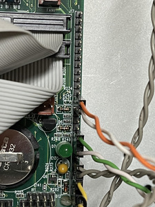
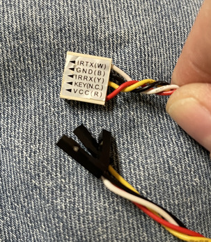
1) The IR harness with pins
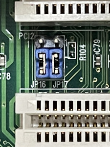
2) The JP16/JP17 showing the 2/3 pins I have it set at.
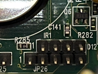
3) the IR1 dedicated IR connector on the motherboard
4) the 1 x 24 “strip” connector that the documentation references
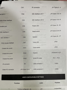
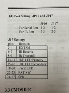
5) The settings from the manual for IR - talking about JP16/17 and which pins on J17 are IR (6-9). (The manual does not speak about the IR header itself.)
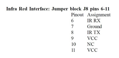
6) Pinouts from the Statson site that also show two IR headers. IR1, and JP17 pins 6-9 both reference IR.
So, what do I use? I checked the four pin IR header (IR1). One pin is ground. Two are getting 5V. One doesn’t register anything. I also checked the four pins on J17. Pin #9 gets 5V and Pin #7 is ground. The other two don’t get anything.
Confused as all get out. Obviously I need to use one of these connectors, but the motherboard makers get a F for not providing more info on the pinouts and which header to use!