Yeah, if you wanna pull together a few datasheets and research it, I can punch out a pcb for you. Just tell me what it needs to do.
That is a particularly perplexing situation though. How one chip could assert dominance over another while in parallel. My guess is there may be a pin for telling the chip to be quiet that is only connected to the lower chip and not the upper. Maybe like a IDE master/slave kinda thing.
Sphere478, have you already seen this article ? Might be helpful for your project. Personally I made this DIY "tophat" years ago but I don't remember if it helped me at least once. I'm even not sure whether it works at all
Does this look like the answer we were waiting for? 🤔
I’m away from computer RN on my phone.
Had a look at this.
Preferably you would control the soldered chip with the active low #CE (Chip Enable) line, disabling the chip by pulling it high. It could also be done by pulling the #OE (Output Enable) line high. The difference between them is that #CE controls the whole chip, while #OE only controls the chip's output. If #CE is high, the chip will be completely disabled with tristated pins, drawing only negligible current. If #OE is high (and #CE low), the chip is initialized, but the data output lines will be tristated, not outputting anything. It'll consume more power, but the advantage is that output is instantly available after pulling #OE low, there's no delay while the chip is initialized. When wanting to permanently disable a chip, using #CE of course makes most sense.
In this particular scenario, there's however a practical problem doing the above. Assuming that the #CE line is hardwired to ground permanently enabling the chip, you can't simply wire a pullup to the #CE pin on the soldered chip to keep it permanently high and leave the original connection. The pin will still be shorted to ground and kept low. There's no way around cutting the connection to the mobo. If the mobo actively controls the #CE line, it would be even more complicated, you'd both have to cut the connection, and wire the control line from the mobo to the new chip.
The approach of the top hat adapter seems to be instead keeping the soldered chip in a permanent reset state (and in extension disabled) by simply hardwiring the active low #RESET pin of the soldered chip to ground. The connection to the mobo trying to pull the #RESET pin high through an assumed resistance can be left in place, the short to ground in the adapter will "win", holding the pin low. No modifications of the mobo required.
In addition to that, it would be a good idea to add a pullup for the new chip's #RESET line in the adapter.
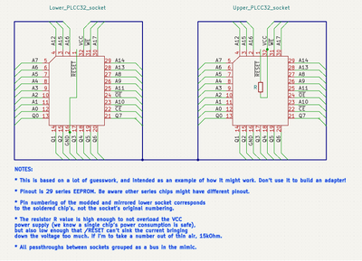
If I were to guess, the top hat adapter looks something like this electrically:
Note "guess". I'm founding this on assumptions of how the control circuitry on the mobo for those pins is designed. Knowing would involve some quite thorough research of a bunch of different mobos. It also assumes that the chip is tristated when the #RESET is active. It likely is, but I don't know for sure. Might also add that the resistor is a precaution, see it as some kind of short circuit protection. It's probably not really needed.
Also almost forgot to mention I based this on 29 series EEPROM pinout. If you got something else, you'll have to adapt it for that.
Hope I made any sense. Precise technical descriptions in foreign languages isn't always my strong suit 😀