VOGONS


First post, by jasa1063

User metadata
Rank Oldbie
Rank
Oldbie

I picked up a PC Chips M326 v5.3 386 motherboard. What I found unusual is that it has both a surface mount 386/40 and a 386 socket. Does anyone have any experience with this specific board? I assume the additional socket is probably for a 486DLC CPU. So far it is running just fine with the onboard 386/40, but I am curious about the additional 386 socket.

Attachments

  • s-l1600 (3).jpg
    Filename
    s-l1600 (3).jpg
    File size
    598.37 KiB
    Views
    684 views
    File license
    Fair use/fair dealing exception
  • s-l1600 (4).jpg
    Filename
    s-l1600 (4).jpg
    File size
    849.06 KiB
    Views
    684 views
    File license
    Fair use/fair dealing exception

Reply 1 of 8, by weedeewee

User metadata
Rank l33t
Rank
l33t

Well...
https://theretroweb.com/motherboards/s/pcchip … nd-up#downloads
the first manual is clearly for earlier revisions of the board,
and the other 'MTL' manual, actually says it's for rev 2.

but both indicate a 486DLC as a possible CPU, and since the main cpu is soldered on the board, the only other option was to have another socket for an upgrade cpu, which as mentioned in the manual would be a 486DLC.
though given no manual, I kinda wonder if there's a jumper to select which cpu should be used, and which one.

Right to repair is fundamental. You own it, you're allowed to fix it.
How To Ask Questions The Smart Way
Do not ask Why !
https://www.vogonswiki.com/index.php/Serial_port

Reply 2 of 8, by keropi

User metadata
Rank l33t++
Rank
l33t++

There is a disable pin on the 386DX cpu - look here: Re: New 486dlc build problem.
It worked fine on a mobo I had with a soldered AM386DX : Re: New 486dlc build problem.
so you can check and see if the #FLT pin goes to some jumper or lift it and connect it to GND

🎵 🎧 PCMIDI MPU , OrpheusII , Action Rewind , Megacard and 🎶GoldLib soundcard website

Reply 3 of 8, by jasa1063

User metadata
Rank Oldbie
Rank
Oldbie

I installed a 486DLC that I had extra just to try it out. The system will not post. I determined jumper J4 is to switch between 33 & 40 MHz. I tried switching J5 but that did not change anything. At this point I am just going to leave well enough alone and run it as a 386/40 MHz system.

Reply 4 of 8, by mathew7

User metadata
Rank Newbie
Rank
Newbie
jasa1063 wrote on 2022-08-21, 20:57:

I installed a 486DLC that I had extra just to try it out. The system will not post. I determined jumper J4 is to switch between 33 & 40 MHz. I tried switching J5 but that did not change anything. At this point I am just going to leave well enough alone and run it as a 386/40 MHz system.

Does your board still work without a socketed CPU?
I have version 5.4, which is very similar. On first look, I can only see differences were the pin headers are.

Reason I ask: I tried to put a 486DLC and a 386DX40 in the socket and I had problems.
What I did:
1. run benchmarks on the board when I got it - everything worked, phils suite ran completely, twice.
2. put a socketed CPU (another AMD 386DX40 and a Cx486DLC) - not work....I think the DX posted, but was unstable, but I don't recall if DLC POSTed.
3. removed socketed CPU - MB POSTed, but re-ran benchmarks and they locked soon after boot
4. removed soldered CPU - either socketd CPUs would POST but still froze in DOS

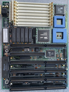
So my conclusion is that the chipset was damaged due to 2 CPUs in parallel. I'm actually looking for a motherboard to take it's chipset (I'm obsessed with the small footprint, like M326, so if I find a larger donor board....)

I see in your photos it says SARC RC4018A4 on a sticker (which I found on your V5.3 and also a V5.5 photo), but I don't have the sticker and it says PC CHIPS 11 (and the smaller chip is 13). I have the same dimples on it (2 big ones on the diagonal of pin 1).
So a big warning against trying again and also I want to find out what actual chipset is used, as I know that most PC CHIPS 386 products are relabeled.
So, anyone can confirm SAR RC4018A4 == PC CHIPS 11 ?? Also, what other chipsets are direct replacements? I'm willing to try.
Edit: based on dimples, I see ALI M1429 (A1) and Bioteq 82C3491 with the same pattern. Anyone can confirm they're the same chip? Again: THIS IS BASED ON PHYSICAL PACKAGE.

Reply 5 of 8, by Deunan

User metadata
Rank Oldbie
Rank
Oldbie
mathew7 wrote on 2023-01-02, 09:42:

So my conclusion is that the chipset was damaged due to 2 CPUs in parallel.

It's not impossible but the first thing to go between two CPUs fighting for the bus is either of them, not the chipset. Frankly I would assume bad BIOS setting, bad RAM or bad cache before condemning the chipset. Swap RAM for another set, completly disable cache in BIOS, pick default or very slow timings and try again. Also, remove co-processor if you installed it and any ISA cards you don't need. In fact test a different I/O and VGA as well. I've dealt with dozens of 386 mobos over the years, and I've modded a few and made mistakes along the way, I have never ever seen a bad chipset.

Reply 6 of 8, by mathew7

User metadata
Rank Newbie
Rank
Newbie
Deunan wrote on 2023-01-02, 17:57:
mathew7 wrote on 2023-01-02, 09:42:

So my conclusion is that the chipset was damaged due to 2 CPUs in parallel.

It's not impossible but the first thing to go between two CPUs fighting for the bus is either of them, not the chipset. Frankly I would assume bad BIOS setting, bad RAM or bad cache before condemning the chipset. Swap RAM for another set, completly disable cache in BIOS, pick default or very slow timings and try again. Also, remove co-processor if you installed it and any ISA cards you don't need. In fact test a different I/O and VGA as well. I've dealt with dozens of 386 mobos over the years, and I've modded a few and made mistakes along the way, I have never ever seen a bad chipset.

I have to contradict you. The ISA combinations you talk were still within design from the start. Longer traces lead to signal degradation due to increased resistance (and lower currents).
But my case is not a designed one. The 2 active CPUs increase the load on the chipset pins. All pins (input AND output) have a current rating which, if exceeded, can damage that pin. Thus, by not disabling the onboard CPU, the chipset would drive 2 CPUs when it was designed for only 1. That certainly results in burning chipset transistors. Of course, it can also damage the CPUs, but the socketed works fine in another MB.

Also I hot-aired away the onboard CPU and it won't post with the socketed one. But that could have been due to tantalums exposed to hot-air.

Reply 7 of 8, by Deunan

User metadata
Rank Oldbie
Rank
Oldbie
mathew7 wrote on 2023-12-01, 12:36:

The 2 active CPUs increase the load on the chipset pins. All pins (input AND output) have a current rating which, if exceeded, can damage that pin. Thus, by not disabling the onboard CPU, the chipset would drive 2 CPUs when it was designed for only 1. That certainly results in burning chipset transistors.

Possibly, not certainly. If your chipset is dead it could've been ESD that damaged it for example. These are CMOS not TTL chips. There aren't any drive currents other than to charge stray capacitances, that is why the CPU traces are so thin and close to each other yet it all works at 40 MHz.

Dry tantalum caps don't degrade in higher temperatures like typical wet electrolytics, if they didn't blow when power was applied I'd say they are still good enough. Frankly the fact that this mobo appears dead now, after a heat cycle (removing the soldered CPU), would prompt me to look for cracked solder on pins or broken traces/vias. It might be that and not chipset damage - but obviously it's up to you if you want to put in all that work. Trying to find a microcrack in a trace or via is a very time consuming process, and often very frustrating too.

Reply 8 of 8, by mathew7

User metadata
Rank Newbie
Rank
Newbie

It works.
After I wrote my previous post, I took a new look and saw a small bridge between A31 and VSS (due to my bad cleaning of the pads after hot-air). It was such a small bridge, that I actually saw it only with one of those cheap USB microscopes (zoom where 4 pads would take my whole screen).
Spent 2 hours afterwards with a 486DLC-40 with stable setup (well, after the normal VGA won't work in that slot, RAM needs re-seating). So chipset is ok.