VOGONS


Reply 20 of 40, by tony359

User metadata
Rank Member
Rank
Member

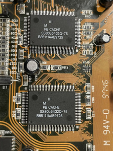
I'm getting to a point where I am ready to give up on this board TBH. I've powered the 3.3V line using my external PSU (it's floating so it can work) and I think I identified a bad cache chip. It would get really hot but only sometimes. I removed it and now the other one gets really hot, but only sometimes???

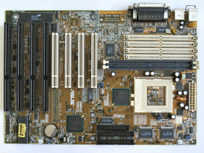
Anyways despite fixing a ton of things on this board it still refuses to boot up, same few instructions executed and then it resets itself with either 72 or 168pin memory modules.

My next step was to re-flash the bios but it seems it's impossible to find - unless someone has any further ideas?

My Youtube channel: https://www.youtube.com/@tony359

Reply 21 of 40, by tony359

User metadata
Rank Member
Rank
Member

Looking at the POST codes, the last code before a reset is 05 which in Award world should mean "keyboard controller initialization". Does anybody think that this could be the issue? Or maybe that's simply the last instruction executed?

Also, how does ATX work on those motherboards with dual AT/ATX inputs? I mean, is there normally a connector on those boards where to connect the front panel push-button? I'm trying to find out whether there may be a jumper left in a weird position which is causing the issue but so far no luck.

Thanks!

My Youtube channel: https://www.youtube.com/@tony359

Reply 22 of 40, by Repo Man11

User metadata
Rank Oldbie
Rank
Oldbie

The only dual connector motherboard I have is an Asus TXP4, and with it all you have to do is connect the ATX power and use a momentary contact switch on the ATX power post on the front panel header (I use the reset switch).

"I'd rather be rich than stupid" - Jack Handey

Reply 23 of 40, by tony359

User metadata
Rank Member
Rank
Member

that's the problem, I do not see an ATX power on the front panel header on any of my dual-PSU motherboards.

Anyways, the board is alive! Indeed something to do with the keyboard controller: I had to remove one "half" of it as it was shorted and the board didn't like that. Once replaced, it came back to life.

Now to the new problem - you wouldn't think that was it, right???

I had to remove a cache chip as it was burning hot. But with only one module the board could not see any cache whatsoever. I tried putting back the one I removed (now the board powers up I thought maybe my diagnosis was incorrect and it would just work) but still burning hot and no cache detected.

As EVERYTHING on this motherboard I cannot find info on those chips. The label is "PB CACHE ss80l6432q-75".
Do you think all cache memory modules share the same pinout and I might be able to replace it with something else? In that case, any ideas? I tried googling the modules from another board but nothing is available to buy.

Attachments

My Youtube channel: https://www.youtube.com/@tony359

Reply 24 of 40, by Repo Man11

User metadata
Rank Oldbie
Rank
Oldbie
tony359 wrote on 2022-10-04, 17:21:
that's the problem, I do not see an ATX power on the front panel header on any of my dual-PSU motherboards. […]
Show full quote

that's the problem, I do not see an ATX power on the front panel header on any of my dual-PSU motherboards.

Anyways, the board is alive! Indeed something to do with the keyboard controller: I had to remove one "half" of it as it was shorted and the board didn't like that. Once replaced, it came back to life.

Now to the new problem - you wouldn't think that was it, right???

I had to remove a cache chip as it was burning hot. But with only one module the board could not see any cache whatsoever. I tried putting back the one I removed (now the board powers up I thought maybe my diagnosis was incorrect and it would just work) but still burning hot and no cache detected.

As EVERYTHING on this motherboard I cannot find info on those chips. The label is "PB CACHE ss80l6432q-75".
Do you think all cache memory modules share the same pinout and I might be able to replace it with something else? In that case, any ideas? I tried googling the modules from another board but nothing is available to buy.

In your first post I can see a header marked ATX switch just below the coin battery.

"I'd rather be rich than stupid" - Jack Handey

Reply 25 of 40, by Repo Man11

User metadata
Rank Oldbie
Rank
Oldbie

There are versions of theTXP4/TXP4-X that had two cache chips; since they are very similar motherboards, maybe those would be something to look up? This was the best quality photo I could find, the chip information should be decipherable.
I have a K6-3+ in my TXP4 and I've found that the memory performance is slightly lower with the motherboard's cache enabled so I have disabled it - obviously not something you'd want to do with any of the Socket 7 CPUs that do not have on die cache.

According to a quick search this appears to be the data sheet for the cache chips on the Asus board: https://html.datasheetq.com/UT6164C32-doc-Utron

Attachments

"I'd rather be rich than stupid" - Jack Handey

Reply 26 of 40, by tony359

User metadata
Rank Member
Rank
Member

In your first post I can see a header marked ATX switch just below the coin battery.

indeed but I'm not sure I know how to use them. Another board I have has similar jumpers but to select the PSUs, not to turn on the PC.
Anyways, the board is starting up now - I thought maybe one of the ATX jumpers were in the wrong place - so not really an issue anymore. But thanks!

I have the UT6164 on one of my boards too and could not find anything online - even though those are the UT6164C64 and not the UT6164C32 you mentioned. I might have found some UMC ones (which I have on another of my boards) from Alibaba, waiting to get some pricing.

To be honest I think I'll fix the 3.3V line - I'm still trying to source a suitable transistor and been using my external PSU for testing - then I will just wrap up the project with "no cache" and might resume it later if/when I get something.

Please feel free to recommend options meanwhile - and THANK YOU a lot for your time on this! 😀

My Youtube channel: https://www.youtube.com/@tony359

Reply 27 of 40, by Sphere478

User metadata
Rank l33t++
Rank
l33t++

I remember another post somewhere where someone was talking about cache chips getting hot, I can’t for the life of me remember what they did to fix it though, seems like in one, they replaced the chip, and in another it just magically started working. Sorry this isn’t much help, maybe you should start with the datasheet, and verrrrrry carefully check to see if the proper voltage is going to the proper pins, verify grounds, and see if the data sheet sheds light on any other pins of interest.

If that all looks good then maybe it is being driven improperly somehow or is just bad.

Too bad the mobo doesn’t have a coast slot. Otherwise could just desolder the chips and pop in a 512k module.

Edit:
Upgrading cache on Super 7 motherboards

Here is one of the threads.

Seems like cpu voltage may have had something to do with it? Odd…

Sphere's PCB projects.
-
Sphere’s socket 5/7 cpu collection.
-
SUCCESSFUL K6-2+ to K6-3+ Full Cache Enable Mod
-
Tyan S1564S to S1564D single to dual processor conversion (also s1563 and s1562)

Reply 28 of 40, by tony359

User metadata
Rank Member
Rank
Member

Thank you for searching for me!

I will surely try probing those chips - I'll have to rely on a different type of chip for the pinout though as virtually NOTHING on this motherboard has datasheet available. It looks like it was manufactured on the cheap side 🤣.

The cache chips work at 3.3V and the 3.3V line was defective. I found it running at 2.2V but the whole line might have got a flash of 5V when the transistor failed, who knows. I've been monitoring CPU voltage and they're fine.

The 3.3V line is currently supplied from a bench PSU (while I find a replacement for the transistor) and I did notice something weird: if I power up the 3.3V line BEFORE giving power to the main PSU, the cache chips immediately overheat (line draws 1.7A-ish) while if I power up the main PSU first and half a second later I power up the 3.3V line, then the 3.3V line current stays low (0.8A) and things stay cooler until I reboot. Still, one of the chips gets warmer than the other one even at lower currents.

Anyways, I'll keep trying, but the fact that the board is alive is a great milestone for me! 😀

My Youtube channel: https://www.youtube.com/@tony359

Reply 29 of 40, by tony359

User metadata
Rank Member
Rank
Member

I've made my usual video for this repair! I hope you like it, let me know what you think! (Vogons mentioned of course!)

https://youtu.be/cwMtuvmFagc

My Youtube channel: https://www.youtube.com/@tony359

Reply 30 of 40, by Sphere478

User metadata
Rank l33t++
Rank
l33t++
tony359 wrote on 2022-10-11, 17:40:

I've made my usual video for this repair! I hope you like it, let me know what you think! (Vogons mentioned of course!)

https://youtu.be/cwMtuvmFagc

Great video 😀

I have some cache chips from a junk 430tx that may interest you.

Sphere's PCB projects.
-
Sphere’s socket 5/7 cpu collection.
-
SUCCESSFUL K6-2+ to K6-3+ Full Cache Enable Mod
-
Tyan S1564S to S1564D single to dual processor conversion (also s1563 and s1562)

Reply 31 of 40, by Sphere478

User metadata
Rank l33t++
Rank
l33t++

Just pulled em off.

Pm me if interested 😀

Attachments

  • image.jpg
    Filename
    image.jpg
    File size
    1.61 MiB
    Views
    824 views
    File license
    Public domain

Sphere's PCB projects.
-
Sphere’s socket 5/7 cpu collection.
-
SUCCESSFUL K6-2+ to K6-3+ Full Cache Enable Mod
-
Tyan S1564S to S1564D single to dual processor conversion (also s1563 and s1562)

Reply 33 of 40, by Sphere478

User metadata
Rank l33t++
Rank
l33t++

256k each btw. So it will max out your 430tx cache.

Sphere's PCB projects.
-
Sphere’s socket 5/7 cpu collection.
-
SUCCESSFUL K6-2+ to K6-3+ Full Cache Enable Mod
-
Tyan S1564S to S1564D single to dual processor conversion (also s1563 and s1562)

Reply 34 of 40, by an3k

User metadata
Rank Newbie
Rank
Newbie
tony359 wrote on 2022-10-11, 17:40:

I've made my usual video for this repair! I hope you like it, let me know what you think! (Vogons mentioned of course!)

https://youtu.be/cwMtuvmFagc

I just stumbled across your video and commented it but going to combine my findings here.

I never did any electronics repair and don't really have a clue about how electricity, transistors, resistors, etc. work. I just started to learn it a few weeks ago. But I always was great at finding stuff on the internet ... so I wanted to know if I'm still good enough and tried to find your components.

1) Transistor
Your D882-Y is a Micro Commercial Components D882-Y-TP -> https://pdf1.alldatasheetde.com/datasheet-pdf … MCC/D882-Y.html
A matching replacement would be a Fairchild KSD882YSTU -> https://www.mouser.de/datasheet/2/308/1/KSD882_D-1810415.pdf

2) Cache
https://www.alibaba.com/product-detail/-ELECT … _731264113.html
https://findcomponents.net/SS80L6432Q-75

3) Tag
Datasheet: https://4donline.ihs.com/images/VipMasterIC/I … EF6B88F2AEB20B8
https://www.questcomp.com/part/4/um61256fs-15/412123833
https://www.pegasus-components.com/en/electro … 56FS15/16767881

I hope I didn't broke any rules by posting all those links. Any feedback, especially on my findings is very welcome!

Reply 35 of 40, by tony359

User metadata
Rank Member
Rank
Member

I think you've done a good job!

I did get in touch with Alibaba but nobody replied and in the end one of my viewer kindly offered to send a set from a junk TX board!

Keep up the good job! 😀

My Youtube channel: https://www.youtube.com/@tony359

Reply 38 of 40, by gnif

User metadata
Rank Newbie
Rank
Newbie
Sphere478 wrote on 2022-10-12, 02:35:

Just pulled em off.

Pm me if interested 😀

I can confirm these are compatible chips electrically, but I can't confirm that they are fast enough (should be though). You may also find compatible modules on PII CPUs or PPro motherboards as these were commonly paired with them being BSRAM compatible (not that anyone in their right mind should be stripping these CPUs/Motherboards unless they are dead beyond recovery)

See: https://www.lpthe.jussieu.fr/~talon/pentiumII.pdf regarding BSRAM
And attached datahseet.

As for undocumented options/configuration, at a guess it looks like those zero ohm resistors (one of which you knocked off) are to select the cache configuration options, specifically R210, R211, R212 and R213. For example R213 connects to pin 16 of the chip, which on the datasheet shows as a NC (No connect), this is likely to pull this pin high/low if a larger capacity cache chip is installed where this is an extra address line. I'd speculate that R212 is selecting that you have 2x cache chips as it looks like it's the VCC/VDD line, and R211 & R210 also are configuring it's size and/or usage. You would need to reverse engineer it to figure out what exactly, but it might be easier with just some trial and error to see what you get. It does look like the failed chip you removed though is the primary one, so I would expect you to have to move the remaining working one across to that position before things would work at all.

Attachments

  • Filename
    TMTIS00024-1.pdf
    File size
    254.81 KiB
    Downloads
    29 downloads
    File license
    Public domain
Last edited by gnif on 2022-10-28, 03:18. Edited 1 time in total.

Reply 39 of 40, by Sphere478

User metadata
Rank l33t++
Rank
l33t++

When the motherboard worked, I ran those chips at 75mhz without issue.

Sphere's PCB projects.
-
Sphere’s socket 5/7 cpu collection.
-
SUCCESSFUL K6-2+ to K6-3+ Full Cache Enable Mod
-
Tyan S1564S to S1564D single to dual processor conversion (also s1563 and s1562)