VOGONS


First post, by tsalat

User metadata
Rank Newbie
Rank
Newbie

Hi,

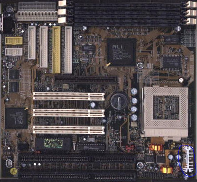
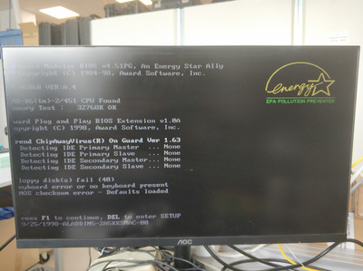
I have recently found an old MOBO at home and tried to resurrect it. However, the board has no post or beep signal with a known good CPU.
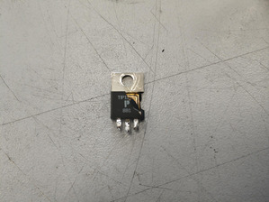
I remember I got this board from someone that tried to OC an K6-2 and got damaged. During my inspection I have found one part, blue circle, to be destroyed. The problem is, I have issues to identify the part, see attachment what is left from it. Any idea what it could be?

thank you, Tomas

Attachments

  • untiled2.jpg
    Filename
    untiled2.jpg
    File size
    116.16 KiB
    Views
    497 views
    File license
    Public domain
  • Untitled.jpg
    Filename
    Untitled.jpg
    File size
    275.9 KiB
    Views
    497 views
    File license
    Public domain

Reply 1 of 8, by DAVE86

User metadata
Rank Newbie
Rank
Newbie

Hello Tomas,

The blown part might be a TIP117 pnp transistor. I'm not 100% sure. I have similar boards laying around so I need to check.
Also it is possible that other parts in the vrm circuit got damaged too.

Reply 2 of 8, by tsalat

User metadata
Rank Newbie
Rank
Newbie
DAVE86 wrote on 2022-09-06, 08:32:

Hello Tomas,

The blown part might be a TIP117 pnp transistor. I'm not 100% sure. I have similar boards laying around so I need to check.
Also it is possible that other parts in the vrm circuit got damaged too.

thank you a lot for your answer. If you could check it, it would be highly appreciated. Yes, aiming to check everything but step by step 😀.
I will keep you updated about the progress, if there will be anything to report.

thank you again, tomas

Reply 3 of 8, by DAVE86

User metadata
Rank Newbie
Rank
Newbie

I looked through my older boards and some pentium and 486 had the pnp transistor chopper vrm circuit. Only found a noname board one with TIP127. I think you might be safe with it if everything else test good.

Reply 4 of 8, by tsalat

User metadata
Rank Newbie
Rank
Newbie
DAVE86 wrote on 2022-09-07, 12:46:

I looked through my older boards and some pentium and 486 had the pnp transistor chopper vrm circuit. Only found a noname board one with TIP127. I think you might be safe with it if everything else test good.

thank you again! I went with the TIP117 mainly because the picture of that destroyed regulator had still TIP11 markings.
And the board is alive, perfect 😀. Very happy about this!

thank you again for the tip, especially the hint with the PNP, helped a lot!

thank you, Tomas

Attachments

Reply 6 of 8, by MyJules

User metadata
Rank Newbie
Rank
Newbie
tsalat wrote on 2022-09-09, 12:49:
thank you again! I went with the TIP117 mainly because the picture of that destroyed regulator had still TIP11 markings. And the […]
Show full quote
DAVE86 wrote on 2022-09-07, 12:46:

I looked through my older boards and some pentium and 486 had the pnp transistor chopper vrm circuit. Only found a noname board one with TIP127. I think you might be safe with it if everything else test good.

thank you again! I went with the TIP117 mainly because the picture of that destroyed regulator had still TIP11 markings.
And the board is alive, perfect 😀. Very happy about this!

thank you again for the tip, especially the hint with the PNP, helped a lot!

thank you, Tomas

hi.

i got a question about your SP-A586B board. Are you using it with ATX or AT PSU? if ATX, how are you turning it on? Jumper block has "PS_ON" but i am not sure if that's for power switch. any info here would be appreciated.

Reply 7 of 8, by tsalat

User metadata
Rank Newbie
Rank
Newbie
MyJules wrote on 2024-04-03, 21:51:
tsalat wrote on 2022-09-09, 12:49:
thank you again! I went with the TIP117 mainly because the picture of that destroyed regulator had still TIP11 markings. And the […]
Show full quote
DAVE86 wrote on 2022-09-07, 12:46:

I looked through my older boards and some pentium and 486 had the pnp transistor chopper vrm circuit. Only found a noname board one with TIP127. I think you might be safe with it if everything else test good.

thank you again! I went with the TIP117 mainly because the picture of that destroyed regulator had still TIP11 markings.
And the board is alive, perfect 😀. Very happy about this!

thank you again for the tip, especially the hint with the PNP, helped a lot!

thank you, Tomas

hi.

i got a question about your SP-A586B board. Are you using it with ATX or AT PSU? if ATX, how are you turning it on? Jumper block has "PS_ON" but i am not sure if that's for power switch. any info here would be appreciated.

Hi,

I was using an AT source but according to this: https://stason.org/TULARC/pc/motherboards/S/S … m-SP-A586B.html, the power button is on CN6 pin 11-12. Just short them down after plug-in the source.

tomas

Reply 8 of 8, by MyJules

User metadata
Rank Newbie
Rank
Newbie
tsalat wrote on 2024-04-04, 15:06:
Hi, […]
Show full quote
MyJules wrote on 2024-04-03, 21:51:
tsalat wrote on 2022-09-09, 12:49:
thank you again! I went with the TIP117 mainly because the picture of that destroyed regulator had still TIP11 markings. And the […]
Show full quote

thank you again! I went with the TIP117 mainly because the picture of that destroyed regulator had still TIP11 markings.
And the board is alive, perfect 😀. Very happy about this!

thank you again for the tip, especially the hint with the PNP, helped a lot!

thank you, Tomas

hi.

i got a question about your SP-A586B board. Are you using it with ATX or AT PSU? if ATX, how are you turning it on? Jumper block has "PS_ON" but i am not sure if that's for power switch. any info here would be appreciated.

Hi,

I was using an AT source but according to this: https://stason.org/TULARC/pc/motherboards/S/S … m-SP-A586B.html, the power button is on CN6 pin 11-12. Just short them down after plug-in the source.

tomas

thx.. it worked ok. though ACPI on this board does not seem to be a good one. Windows only seems to see APM.