Reply 20 of 152, by Sphere478

Rank
l33t++
- Rank
- l33t++
That may be even more of a mess than the one we just did haha.
That may be even more of a mess than the one we just did haha.
Even more messy? Probably about the same. Not needed: VRM, fan header, trimmer, etc. Might need 8-layers? If it can be done in 6 layers, that will be impressive. I think user AC mentioned that Evergreen Technologies used to make these rotator boards, but nobody has ever seen one.
Plan your life wisely, you'll be dead before you know it.
I suppose the power pins will be easy as they will just have planes.
I suppose I could look into the routing.
It will have to be offset, or smd. Preference?
snufkin wrote on 2022-10-07, 12:31:Assuming Vout is 4V and Vin is 5V, then that TO220 package is burning 1W/Amp. Thermal resistance is probably around 75C/W (no heatsink, so just case to ambient). Maximum temperature is around 125C. So maximum power burnt in the regulator is 125/75=1 2/3W. So the CPU can't be drawing any more than a bit over 1.5A max. I'd worry about any linear regulator sandwiched between motherboard and CPU PCB.
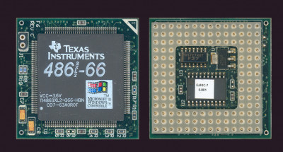
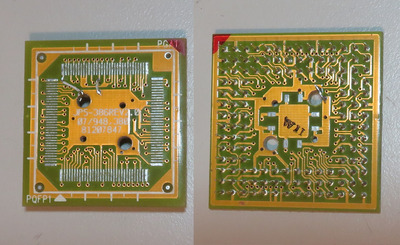
By the way, Evergreen put the 1117 regulator under the PCB as well. See attached. I'm not sure how much difference there is in the power draws of the two, but the BL3 has 16 KB L1 and the SXL2-66 has 8 KB.
Plan your life wisely, you'll be dead before you know it.
Following up on my previous message - Alaris Cougar supplies 4V to the BL3 chip.
What about the 16-bit variant of the BL3? I recall you had one of these boards as well.
Plan your life wisely, you'll be dead before you know it.
Keep in mind that Cougar + BL3 is not fully stable at 3x33 MHz with default voltage and air cooling.
Will know soon if Peltier takes care of things otherwise no idea how to increase the CPU voltage if more than 4V are needed for improved stability.
Will check the Alaris Leopard's CPU voltage tomorrow.
Not sure if it is relevant to the discussion here, or is it ?
I think it is relevant enough. It is the same CPU with half the bus width. So if it too is run at 4.0+ voltages, then another tally for these running at high voltages. If it is way down at 3.5 V, it offers less information. Plus, I don't think there's going to be another thread showing running voltages of IBM Blue Lightning chips.
I'm also concerned about going over 4 V for these BL3 chips. This is primarily because the 1117's dropout voltage, which is around 1.1 V at 500 mA, or 1.3 V at 800 mA. Assuming the BL3 uses 0.5 W, then the max voltage the regulator can run this chip at is 3.9 V. At which point, there isn't much purpose in adding the trimmer. I just as well set it with a resistor to run at the max voltage of the 1117. Alternately, I might need to start looking for an ultra low dropout voltage SOT-223 regulator.
I had deliberately selected an ultra low dropout for the custom SXL2-66 interposer for this reason - that is, if I had to take the CPU up to 4.5 V. I also selected a VRM which didn't get hot at 650 mA running.
Plan your life wisely, you'll be dead before you know it.
Good point about the BL3 voltage thread.
3.815V for the 16-bit BL3 CPU in Alaris Leopard.
With this voltage it runs really well at 2x40 MHz.
feipoa wrote on 2022-10-10, 10:33:snufkin wrote on 2022-10-07, 12:31:Assuming Vout is 4V and Vin is 5V, then that TO220 package is burning 1W/Amp. Thermal resistance is probably around 75C/W (no heatsink, so just case to ambient). Maximum temperature is around 125C. So maximum power burnt in the regulator is 125/75=1 2/3W. So the CPU can't be drawing any more than a bit over 1.5A max. I'd worry about any linear regulator sandwiched between motherboard and CPU PCB.
By the way, Evergreen put the 1117 regulator under the PCB as well. See attached. I'm not sure how much difference there is in the power draws of the two, but the BL3 has 16 KB L1 and the SXL2-66 has 8 KB.
SXL2-66_QFP144_Upgrade.jpg
Fair enough, I'm probably just being paranoid as it looks like putting a heating element in a small oven.
feipoa wrote on 2022-10-11, 06:10:I'm also concerned about going over 4 V for these BL3 chips. This is primarily because the 1117's dropout voltage, which is around 1.1 V at 500 mA, or 1.3 V at 800 mA. Assuming the BL3 uses 0.5 W, then the max voltage the regulator can run this chip at is 3.9 V. At which point, there isn't much purpose in adding the trimmer. I just as well set it with a resistor to run at the max voltage of the 1117. Alternately, I might need to start looking for an ultra low dropout voltage SOT-223 regulator.
For the regulator it looks like the Buffalo BL3-75 is a bit of an outlier at 4.14V, so maybe the 1117 is ok? I can't just see any ULDO SOT-223, so might need to use a different small package. There's the MCP1726 which comes in both SOIC8 which has a pretty terrible 163C/W but can be hand soldered easily, or DFN which is much better at 64C/W but is fiddly. The SOIC would probably just about cope with 500mA going from 5V down to 3.5V.
I don't think that socket stack can be improved upon, it's awesome. Just needs a small flag pole and flag at the top so the electrons know they've reached the summit and can go back down again.
I still may put the VRM on the surface because the VRM would look kind of bare by itself up there. Not shown are the caps. I still haven't drilled the vias but will sometime this week. These interposers aren't rare and aren't valuable, so I do not feel any loss. The interposer shown I got for free and I got a spare for $5.
I also briefly looked for an ultra low dropout VRM in SOT-223, months ago, but didn't find any.
You are the first one to appreciate my tower of inductance. I admit that it grew on me after a week.
Plan your life wisely, you'll be dead before you know it.
Closest alternative might be this: https://www.digikey.ca/en/products/detail/tex … 2501DCQ/1672743
Plan your life wisely, you'll be dead before you know it.
feipoa wrote on 2022-10-12, 01:17:You are the first one to appreciate my tower of inductance. I admit that it grew on me after a week.
I think for me it's the stubbornness of it. It it was just 3 or 4 then it's just messy. By the time you get to, what, 20?, there's a sense of something that isn't meant to work, but someone's going to to make it work anyway.
Back on modding the PGA->PQFP, given that burying the regulator is something that has worked for other designs then why not stick with that? Then, rather than taking wires through the vias I think you can get away with making 4 cuts and drilling only 3 vias (2 small, 1 large), which I've had a go at sketching. That would let you take Vin from one of the existing pads and connect Vout to one of the other pads. That also means that all the Vcc pins on the PQFP side are connected. If there's room for that 5 pin SOT that you found then there should also be room for a couple of 10uF ceramics caps and a 120k resistor between the Feedback pin and Ground. Then you just need one wire for the Feedback to go through to the accessible resistor on the PQFP side (maybe a 220k resistor in series with a 100k pot? Think that'd give Vout range of 3.5V -> 4.5V), with the other side of the resistor to a Vcc pin.
I'm still not a fan of burying the regulator, but can't deny that it had worked elsewhere and it would be tidy. I think the tab on the package is Ground, which you can solder to that central Gnd copper area to help a bit with heat removal.
[edit: could just remove the 3 pins at the top, top-right and right areas, then it's just one cut and 3 vias to remove. Bit less damage to the board and easier to revert.]
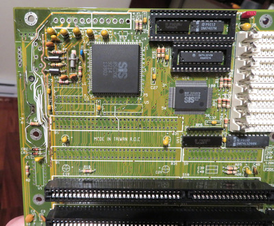
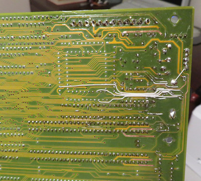
Pardon my delay in replying. I have been working on this mess (attached), which is a board I wanted to test my BL3 hack on. It is one of the more involved battery acid repair jobs I've undertaken.
Now I'm back to thinking about this BL3 adapter. I like how your method reduces the number of vias drilled and generally simplifies the work, however I am troubled by the limited number of PGA Vcc pins which are connected. The PGA-132 normally has 19x Vcc pins. This PGA-to-QFP adapter board only has 8 of these pins hooked up. To remove another 3x Vcc pins doesn't sit well with me. These machine pin sockets on 386 boards tend to loosen over time, especially with our retro hobby tinkering, so I'd like to keep all 8x Vcc pins connected to the motherboard for power.
I do like the idea of using the ultra low dropout regulator, however I wasn't planning on putting in another digikey or mouser order until after I tested my SXL2-66 alpha boards. Looking at the spec sheet for the TPS72501DCQ, they are recommending a 120 K-ohm to set the divider current for 10 uA. Thus, to achieve 3.5 V to 4.5 V output, I would need a trim pot which can adjust from 224K to 323K. This translates to a 500K trimpot. For the small profile I'm after, this would be 3269X-1-504LF https://www.digikey.ca/en/products/detail/bou … 1-504LF/1817536 . Digikey doesn't stock this, but mouser does. However, my next order needs to be from digikey because mouser doesn't have some solder paste syringe tips I need. So I thought maybe digikey would have this larger variety of the side screw trimpot, but they are non-stocked items as well https://www.digikey.ca/en/products/detail/bou … -504RLF/3722155 So I'd have to order it from mouser, but with shipping, that's $15 for a trimpot. So....
Another idea is to use the stocked 100K trim pot, https://www.digikey.ca/en/products/detail/bou … 1-104LF/1817533 , but add a 120K resister in series. The disadvantages would be needing 14 full turns to get the 3.5 to 4.5 V range and running out of space at the fringe edges for fine tuning.
At this point, I think I will stick with the 1117 to see how this makes out. I can always change things later on. I won't be gluing them down at this stage. I will stick with my original plan of drilling out all the vias. I think I will put the 1117 on the top face, just so that the fan on the heatsink helps to some extent.
Would connecting Vout tab on 1117 to that large copper ring going around the perimeter of the interposer board be an issue? It is not connected to anything. I thought it would be GND, but it is not. Or will doing this cause a bunch of noise? When I think back to my old radio's AM antenna, it was a loop. If connecting this loop to Vcc is a bad idea, I can just run a single wire to the central ground plane. Then should I connect this perimeter loop to GND?
Note that the copper ring on the bottom surface of the interposer is connected to GND, just not the top surface ring.
Plan your life wisely, you'll be dead before you know it.
feipoa wrote on 2022-10-15, 10:42:Pardon my delay in replying. I have been working on this mess (attached), which is a board I wanted to test my BL3 hack on. It is one of the more involved battery acid repair jobs I've undertaken.
Tricky bit of surgery.
Now I'm back to thinking about this BL3 adapter. I like how your method reduces the number of vias drilled and generally simplifies the work, however I am troubled by the limited number of PGA Vcc pins which are connected. The PGA-132 normally has 19x Vcc pins. This PGA-to-QFP adapter board only has 8 of these pins hooked up. To remove another 3x Vcc pins doesn't sit well with me. These machine pin sockets on 386 boards tend to loosen over time, especially with our retro hobby tinkering, so I'd like to keep all 8x Vcc pins connected to the motherboard for power.
I'm not certain, but I think that the reason for having multiple Vcc pins is that the internal bond wires from pin to silicon are thin enough that they need to have Vcc connected to the metal layer on the chip in multiple places. So it's less about the maximum current per pin and more about having a good distribution of supply around the chip. If I'm right about that then I'd be more worried about leaving the Vcc pins 85 and 99 on the QFP disconnected. Making the cuts I suggested leaves all the Vcc pins on the PQFP connected. It does leave only 5 PGA pins being used for supply, but each pin can probably handle about an amp, when it sounds like the chip probably only needs around 0.5A.
To be honest, this probably works either way. If you do drill all the vias then it might be interesting to see if bodging a couple of wires to get Vcc to pins 85 & 99 makes any difference at all to the minimum stable voltage.
Another idea is to use the stocked 100K trim pot, https://www.digikey.ca/en/products/detail/bou … 1-104LF/1817533 , but add a 120K resister in series. The disadvantages would be needing 14 full turns to get the 3.5 to 4.5 V range and running out of space at the fringe edges for fine tuning.
I think that's similar to what I'd been thinking, mostly because the series resistor stops the voltage being set too high or too low. I think it would need to be a 220k resistor though, so the resistance range is 220k -> 320k. I can see the problem with having to make lots of turns on a small trim pot.
At this point, I think I will stick with the 1117 to see how this makes out. I can always change things later on. I won't be gluing them down at this stage. I will stick with my original plan of drilling out all the vias. I think I will put the 1117 on the top face, just so that the fan on the heatsink helps to some extent.
Tiny bit of air movement makes a surprising (at least, I find it surprising) difference for heat removal, even with no heatsink, so that should let you drop the voltage a bit more without burning the regulator. Mind that with the 1117 the tab is Vout when on the 72501 it's Gnd.
Would connecting Vout tab on 1117 to that large copper ring going around the perimeter of the interposer board be an issue? It is not connected to anything. I thought it would be GND, but it is not. Or will doing this cause a bunch of noise? When I think back to my old radio's AM antenna, it was a loop. If connecting this loop to Vcc is a bad idea, I can just run a single wire to the central ground plane. Then should I connect this perimeter loop to GND?
Note that the copper ring on the bottom surface of the interposer is connected to GND, just not the top surface ring.
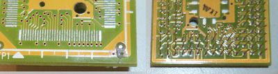
I can't quite tell from the photos, but it looks like maybe there's a plated via near the label PGA1 on the PQFP side, but it's not there on the PGA side. Does if maybe connect to to pin A1 on the PGA side? If it does then that's a PGA Vcc pin. I'd be slightly wary of connecting anything to it, and with the airflow from the fan then it shouldn't be needed.
I might be less worried if it was a ZIF, but some of these worn out machine pin contacts can be fairly loose with poor contact. I'm going to keep all 8 Vcc pins connected. If the motherboard's PGA132 socket was new and the pins on the interposer new, and I would never be moving CPUs in and out often, I'd be less resistant to using just 5 Vcc pins.
Yes, I do plan on reconnecting QFP pins 85 and 99 with 30 AWG. Same as those shown in the motherboard repair above.
Yeah, 220K SMD resistor. Was a typo on the 120K.
No, those plated vias aren't connected to any PGA pin on the other side. I measured them all previously.
Ideally, I'd like to use that perimeter trace for the VRM's tab for purposes of 1) holding the IC down, 2) help some with heat dissipation, 3) having more connection points to the central power plane at 4 corners with bodge wires. My main concern was for noise on Vcc3. If I were to make that perimeter trace GND, there's no direct GND on the VRM to use this perimeter trace for holding down purposes.
Those plated vias - I was planning on using at least one of them to hold the mini trimpot in place, and perhaps the other one to hold the VRM down, that is, assuming I don't use the perimeter trace for the later.
Plan your life wisely, you'll be dead before you know it.
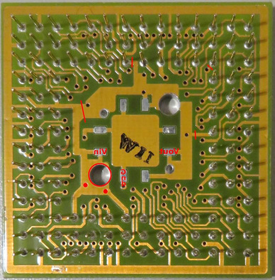
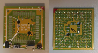
Here's the interposer with all the vias drilled, pins 85 & 99 reconnected, and the 5V ground plane reconnected.
I've decided that I will ground that top surface perimeter trace. It will make connection to components convenient.
Plan your life wisely, you'll be dead before you know it.
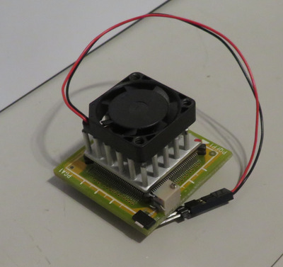
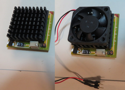
I finished wiring up the components. I decided to use 28 AGW for Vin and Vout of the regulator instead of my regular 30 AWG. The wire width barely makes clearance of the CPU.
For the fan, I drilled two holes through the PCB. This way, I won't have to glue on a header.
I also attached the top perimeter to ground. It made mounting components easy and glueless. For now, I just have double-sided tape holding the VRM in place. I haven't soldered the CPU on yet.
I cut this black heatsink to 32mm x 32 mm to try an optimise the space. This way I can also use a 30 mm fan, rather than 25 mm. I haven't removed the factory heatsink from the BL3 CPU. I'm a little nervous about doing this. Has anyone removed this particular IODATA heatsink before? If so, how did you do it?
Plan your life wisely, you'll be dead before you know it.
Removing heatsinks: heating up the heatsink is usually a handy tactic. I use a torch on low setting. Avoid any contact to flame except the heatsink.
I'm hesitant to heat up the heatsink again. I don't have enough experience determining the melting point of thermal epoxy.
Plan your life wisely, you'll be dead before you know it.
