VOGONS


Sad Voodoo 3

Topic actions

First post, by quicknick

User metadata
Rank Oldbie
Rank
Oldbie

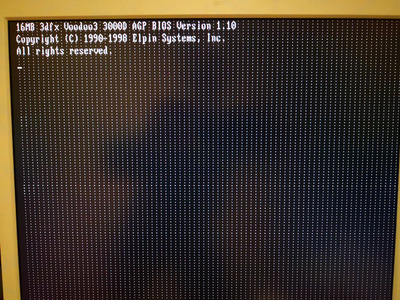
Got this Voodoo 3 from today's flea market, but when I got home it turned out that the green spots that looked like corrosion were really corrosion 😐
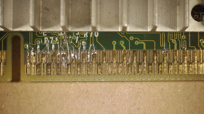
They even reacted (bubbled) when I bathed the card in vinegar, so who knows, maybe the card was stored together with some leaky 286 boards or whatever. Here's how the most damaged part looks like, after scraping most of the green gunk and lightly sanding the 'fingers' :

20221015_213950.JPG
Filename
20221015_213950.JPG
File size
1.83 MiB
Views
602 views
File license
Fair use/fair dealing exception

I'd say it's pretty bad, gaps on at least two traces (Vddq 3.3, AD17) and a few more that definitely need reinforcing. Soldering on/near AGP fingers gives me the shivers, and I can almost envisage all their surface engulfed in solder...

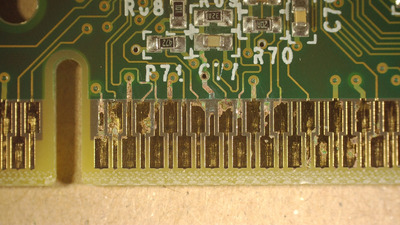
There's also some corrosion between the top RAM chips and on a couple of vias near the vBIOS, but these areas don't look nearly as bad as the one near the AGP connector. I'll leave here a few more photos:

https://imgur.com/a/ZIx6wEo

So, any ideas on how I should tackle this? Bin the card, pray to the Voodoo gods, try to bridge the gaps with very fine strands of copper wire? Is kapton tape suitable for keeping the solder from 'wetting' the entire golden finger when soldering on it?

Reply 1 of 6, by Sphere478

User metadata
Rank l33t++
Rank
l33t++

Tin them. The broken traces may be tricky. Being that that area inserts into the slot. Use very small wire.

Sphere's PCB projects.
-
Sphere’s socket 5/7 cpu collection.
-
SUCCESSFUL K6-2+ to K6-3+ Full Cache Enable Mod
-
Tyan S1564S to S1564D single to dual processor conversion (also s1563 and s1562)

Reply 2 of 6, by pentiumspeed

User metadata
Rank l33t
Rank
l33t

The proper fix is find an scarifical AGP card with same contact finger design, nick and cut tracks, peel off damaged contacts, same time do same to salvage AGP card, cut longer track attached to the contact finger, scrape bare copper first, nick a edge and peel off a good contact, using high temp epoxy glue them down over lapping original bare track and wait for epoxy to cure. Once done, bridge the bare track to tail end of replacement track where contact is with small wire and solder, flux.

This is professional track repair where there is absolutely no choice. This is done on irreplaceable expensive boards too.

I have done peeling the tracks before to do repairs.

Absolutely cannot have tinned contact in high speed circuits as this can cause intermittent issues as soldered layer oxidizes over time.

Cheers,

Great Northern aka Canada.

Reply 3 of 6, by Horun

User metadata
Rank l33t++
Rank
l33t++

Actually because AGP slots do use alternating "staggered height pinchers" in the slot, those thin traces above the fatter bottom conductor part never get touched by the pinchers so you could use a thin (meaning able to paint a very non-thick line) good conductive paint (silver based, not graphite based) or even silver based "wire glue"(if done correctly) on the traces that go inside the slot. The trick will be to keep your created trace as flat as possible.
For above the slot in the green enameled area you can tin, solder wire, whatever... because they are just like any other board trace but as pentiumspeed mentioned over time the solder can degrade...
just a thought and much easier than stripping traces off a donor card. forgot to mention: I would NOT try to solder/Tin or use any wire that goes down into the AGP slot.

Hate posting a reply and then have to edit it because it made no sense 😁 First computer was an IBM 3270 workstation with CGA monitor. Stuff: https://archive.org/details/@horun

Reply 4 of 6, by quicknick

User metadata
Rank Oldbie
Rank
Oldbie

Thank you all for your input. Not particularly proud of how this turned out, but I had to quickly check if the card is at least a bit alive so pentiumspeed's method was out of the question (mainly because I'm lacking the high-temp epoxy and the experience 😁 )

20221018_003801r.jpg
Filename
20221018_003801r.jpg
File size
970.62 KiB
Views
430 views
File license
Fair use/fair dealing exception

At the initial check-up I found 4 broken traces, but more of them broke up at the boundary between the gold-plated finger and plain copper when I went over them with the soldering iron, so it ended up with 13 bridge wires (not all were needed, but I put them on all traces that looked very bad). Some of the larger traces were ok with just tinning. The end-result fits nicely in the socket, and it has survived at least one insertion and removal cycle 😁
The Voodoo's alive, but it's not very healthy:

IMG_20221017_224648r.jpg
Filename
IMG_20221017_224648r.jpg
File size
661.2 KiB
Views
430 views
File license
Fair use/fair dealing exception
IMG_20221017_224555r.jpg
Filename
IMG_20221017_224555r.jpg
File size
546.01 KiB
Views
430 views
File license
Fair use/fair dealing exception

This means more work to do, checking for discontinuities around the upper four RAM chips. I'll come back with an update in the next few days.

Reply 5 of 6, by Sphere478

User metadata
Rank l33t++
Rank
l33t++

For such small work, that is pretty good.

Sphere's PCB projects.
-
Sphere’s socket 5/7 cpu collection.
-
SUCCESSFUL K6-2+ to K6-3+ Full Cache Enable Mod
-
Tyan S1564S to S1564D single to dual processor conversion (also s1563 and s1562)

Reply 6 of 6, by Thermalwrong

User metadata
Rank Oldbie
Rank
Oldbie

Nice job fixing that, it looks quite tidy 😀
I have a Voodoo 3 that's got the same mess on the screen, but that's my fault for flexing the card fitting a screw-on heatsink. I think I detached one of the BGA pads for the memory potentially.