Reply 20 of 52, by rasz_pl
Rank
l33t
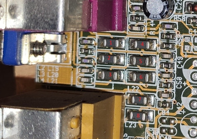
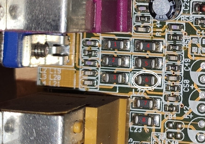
hmm, using Roman555 provided diagram as a reference trace one of the RGB signals all the way to the chip and measure resistance to ground at each point of the filter
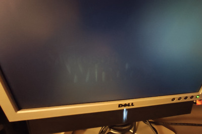
Im running out of ideas, its getting its supply, DAC reference is internal, what else could influence all 3 analog channels? bad blanking? check with another monitor? slap an oscilloscope on the output signals(rgb and VH syncs)?