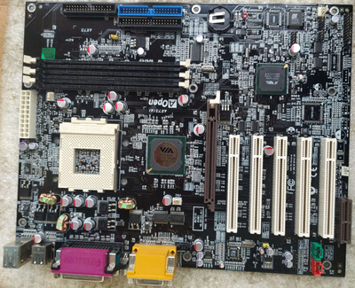
maekawa wrote on 2022-12-25, 20:11:A typical VRM has approximately 8 filter capacitors (eg GA-BX2000).
So calculating the combined ESR gives (theoretical value wit […]
Show full quote
A typical VRM has approximately 8 filter capacitors (eg GA-BX2000).
So calculating the combined ESR gives (theoretical value without considering wire resistance):
YXF: 0.16ohm / 8 = 0.02ohm
ZLJ: 0.059 / 8 = 0.007375 ohm
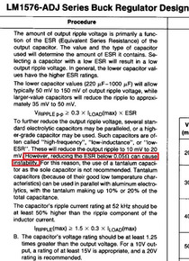
In LDOs, tantalum capacitors and electrolytic capacitors cannot be replaced with MLCCs and polymer capacitors due to their phase margin (having ESR limits), but what about VRMs?
The term VRM isn't the best fit for what you mean. "VRM" is a "voltage reduction module", and early VRMs (on 486 boards) often were in fact impemented using linear regulation for example with the LM1086 LDO regulator chip. You can express more clearly what you mean by using the term "(step down) switch-mode regulator". As far as I know, there are no known minimum ESR values for most switch-mode implementations, so you are most likely fine.
maekawa wrote on 2022-12-25, 20:11:
Also(1): I don't think it oscillates the signal by replacing the filter capacitors (for PI and EMC) far from the VRM with any low ESR. However, it improves emissions but worsens immunity.
Exactly so. Caps "far away" from a switch-mode regulator would not cause instability, because the trace resistance and inductance adds to the apparent ESR/ESL at the regulator. So even in case they would use one of the ESR-sensitive LDOs to generate the rail, instability is unlikely. You should also keep in mind that the ESR issue about instability only applies on the output of the regulator, not on the input. Caps to smooth the 5V or 3.3V (on ATX boards) supply, that get directly fed from the PC power supply can be as low ESR as you want. The most delicate position is the output filter caps of the core voltage regultor.
maekawa wrote on 2022-12-25, 20:11:
Also(2): Can I use one or two SEPC 6.3V 1000uF (0.018ohm) instead of YXG 6.3V 1000uF *8?
SEPC ripple current is 3530mArms and YXG is 840mArms.
While you get good enough ripple current handling capability and low enough ESR with those caps, dropping the capacitance to a quarter of the original value is something I would not blindly recommend. The factor that determines the amount of output ripple is acutally the total impedance of the capacitor bank, which is the result of of the ESR, the ESL (the lower, the less impedance) and the capacitance (the higher, the less impedance). You could do a rough calculation on how much the capacitance of 8mF or 2mF contributes to the total impedance at around 500kHz (a typical switching frequency for the core voltage regulator) to determine whether dropping the capacitance is significant. Ignore the contribution of the ESL (equivalent series inductance) for the moment.
In a nutshell: Physical fact: ESR + capacitance determines the amount of ripple, and ripple current rating determines the longevity of the replacement caps. Personal experience: If you find brand caps with sufficiently high current rating at the original capacity, you nearly always also match ESR requirements.