VOGONS


Reply 20 of 26, by mkarcher

User metadata
Rank l33t
Rank
l33t
pico1180 wrote on 2023-01-05, 13:26:

here is what i found for the mem configuration, but it seems a little vague to me. i'm guessing the 1-s indicates one single sided memory module? it indicates it will accept double sided, but doesn't give any double sided configurations?

If I had to guess, I read "Double Side is Bank 0, Bank 2 or Bank 1, Bank 3" as "the first side of bank 0 is wired in parallel to the second side of bank 1; the second side of bank 0 is wired in parallel to the first side of bank 1" (same for bank 2/3), so you can insert a double-sided modules in banks 0 and 2, or in banks 1 and 3, but not in 0 and 1. A double sided module in bank 0 would work like a single-sided module in bank 0 and a single sided module in bank 1. So the rules for that board are obviously: It supports only a single bank size, which can be 1M, 4M or 16M. You need to fill the banks in order: bank 0 first, than bank 1 (possibly as second side of a dual-sided module in bank 0), and then bank 2 and 3 at the same time. That's a quite inflexible memory configuration scheme for a 486 board. Many 386 boards were accomodating a higher variety of configurations.
If bank 0 is broken, you will not get the board working, no matter what you do with the other banks.
Reply 21 of 26, by pico1180

User metadata
Rank Member
Rank
Member
CoffeeOne wrote on 2023-01-05, 14:23:

OK, so did you already try a single 4MB module 72pin in bank0 without any 30pin SIMMs?
Bank 0 is the one next the 30pin slots.

EDIT: I screwed up the quoting, so deleted everything 😁

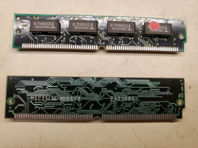
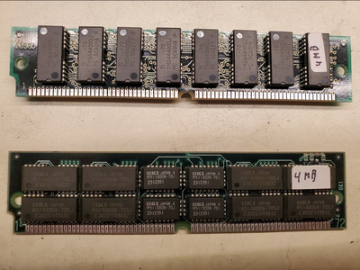
I di try a single 4MB module to no luck. See pic for the modules I tried. They are the only 4MB modules I have. Maybe there is something about them that make them incompatible?

Attachments

Reply 22 of 26, by mkarcher

User metadata
Rank l33t
Rank
l33t
pico1180 wrote on 2023-01-11, 03:41:

I di try a single 4MB module to no luck. See pic for the modules I tried. They are the only 4MB modules I have. Maybe there is something about them that make them incompatible?

The first and second module don't include parity bits. This might be a problem, depending on the board. The last one is supposed to be perfectly fine. It's exactly the same chips as you would find on 4*1MB 3-chip 30-pin SIMMs. If that one doesn't work in the slot right next to the 30-pin SIMM sockets, there definitely is a problem, possibly a broken trace on the board connecting the 30-pin to the 72-pin socket.

Reply 23 of 26, by pico1180

User metadata
Rank Member
Rank
Member
mkarcher wrote on 2023-01-11, 06:46:
pico1180 wrote on 2023-01-11, 03:41:

I di try a single 4MB module to no luck. See pic for the modules I tried. They are the only 4MB modules I have. Maybe there is something about them that make them incompatible?

The first and second module don't include parity bits. This might be a problem, depending on the board. The last one is supposed to be perfectly fine. It's exactly the same chips as you would find on 4*1MB 3-chip 30-pin SIMMs. If that one doesn't work in the slot right next to the 30-pin SIMM sockets, there definitely is a problem, possibly a broken trace on the board connecting the 30-pin to the 72-pin socket.

my pics were confusing and I did that poorly. the front and back did of the modules did not properly correlate. the inserted photos below properly correlate to the front and back of their respective module. one photo is one module, the other photo is the other module.

Attachments

  • mem 2.jpg
    Filename
    mem 2.jpg
    File size
    369.92 KiB
    Views
    258 views
    File license
    Public domain
  • mem 1.png
    Filename
    mem 1.png
    File size
    420.41 KiB
    Views
    258 views
    File license
    Public domain

Reply 24 of 26, by mkarcher

User metadata
Rank l33t
Rank
l33t
pico1180 wrote on 2023-01-11, 16:55:

my pics were confusing and I did that poorly. the front and back did of the modules did not properly correlate. the inserted photos below properly correlate to the front and back of their respective module. one photo is one module, the other photo is the other module.

OK, I get it now. I could have known that my interpretation of three different modules (only the back of one being shown) was wrong, if I had taken a close look at the PCB with just 4 chips. Those are just the parity bits, and they can't be used to build a 4MB SIMM. I just glanced over the suspected front of a different module and expected it to be 1Mx8 chips, so four of them would be enough for a complete non-parity 1Mx32 SIMM.

Both of these modules should work perfectly in a 72-pin slot that is wired in parallel with 4 30-pin slots, if 4*1MB works in those 30-pin slots. It's electrically identical: You have 8 chips of 1M x 4 for 32 data bits and 4 chips of 1M x 1 for 4 parity bits, yielding 1M x 36 in total.

Reply 25 of 26, by pico1180

User metadata
Rank Member
Rank
Member
mkarcher wrote on 2023-01-11, 18:46:
pico1180 wrote on 2023-01-11, 16:55:

my pics were confusing and I did that poorly. the front and back did of the modules did not properly correlate. the inserted photos below properly correlate to the front and back of their respective module. one photo is one module, the other photo is the other module.

OK, I get it now. I could have known that my interpretation of three different modules (only the back of one being shown) was wrong, if I had taken a close look at the PCB with just 4 chips. Those are just the parity bits, and they can't be used to build a 4MB SIMM. I just glanced over the suspected front of a different module and expected it to be 1Mx8 chips, so four of them would be enough for a complete non-parity 1Mx32 SIMM.

Both of these modules should work perfectly in a 72-pin slot that is wired in parallel with 4 30-pin slots, if 4*1MB works in those 30-pin slots. It's electrically identical: You have 8 chips of 1M x 4 for 32 data bits and 4 chips of 1M x 1 for 4 parity bits, yielding 1M x 36 in total.

Thank you for your help on this. Sure enough, there was a broken trace on the back of the board. I did a trace repair and now the board is working perfectly.

Attachments

  • DSC09024.JPG
    Filename
    DSC09024.JPG
    File size
    1.55 MiB
    Views
    233 views
    File license
    Public domain

Reply 26 of 26, by mkarcher

User metadata
Rank l33t
Rank
l33t
pico1180 wrote on 2023-01-14, 06:21:

Thank you for your help on this. Sure enough, there was a broken trace on the back of the board. I did a trace repair and now the board is working perfectly.

Great that you could fix that board! If you want it to look more pretty, you can remove the flux residue (that's the transparent gunk at the place you soldered) easily using isopropyl alcohol as solvent. To prevent short circuits caused by metal touching the fixed trace, you want to paint it with nail polish. Flux can easily be penetrated/scratched and doesn't work as reliable insulation.