First post, by JonF
- Rank
- Newbie
Hi all, I have an IBM 5175 PGA display. It is a neat little CRT. I've read it was a common mod in the past to convert these to have a standard 15 pin VGA cable. I am having trouble figuring out how this mod would deal with different sync polarities at resolutions other than 640x480.
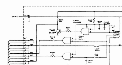
So, I think the 5175 internal sync processing is setup to take combined H&V sync. It then splits the H & V, and runs it through a CD4093B IC before sending to the analog board. I have only been able to get the monitor to sync to negative sync polarities. Either with composite or using clip leads to inject H and V separately on the video board.
Video cards are setup to run different polarities for sync at different resolutions, presumably to help multisync monitors ID the signal.
Horizonal Dots 640 640 640
Vertical Scan Lines 350 400 480
Horiz. Sync Polarity POS NEG NEG
Vert. Sync Polarity NEG POS NEG
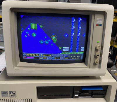
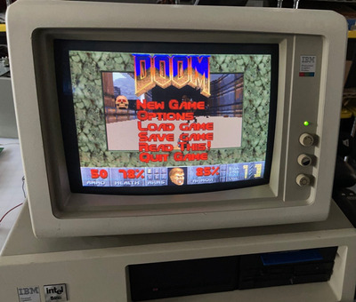
So for 640x480 everything is great. Monitor will sync OK without an Extron box in the mix. However for other resolutions ie during DOS boot, command line, etc, one of the sync lines is positive and the monitor won't sync. Unless I use an Extron box to force composite sync(which is negative) or negative HV sync.
So, any ideas on how to make this monitor work without lugging around an Extron box or trying to wire one up inside the monitor case? Any one out there have an already modded 5175 they can share pictures of the insides?
Thanks!