Reply 40 of 41, by anetanel
Deunan wrote on 2023-03-28, 11:33:If you are not in a hurry you can wash that PCB in running water. Some solid soap and a brush with long hair will help clean the […]
anetanel wrote on 2023-03-28, 10:57:I will do as you said and start examining the components to the best of my ability.
I started with overlaying the pcb solder side over the component side so it will be easier to identify each component from the back.If you are not in a hurry you can wash that PCB in running water. Some solid soap and a brush with long hair will help clean the difficult to reach spots. Leave it be for 1-2 days to dry completly in room temperature (you can inspect it during that time but not connect to mains). Cleaning helps spot burn marks and also removes possible accumulation of dirt that could get conductive with enough ambient humidity.
At this point you are most interested in the parts between the smaller transformer and the transistors. The power resistor and a ceramic disc capacitor next to it are most likely the snubber circuit (R4 + C8 per the schematic I've linked). The big blue cap is C7 on the schematic, make sure it's not shorted. This particular cap should in theory prevent a direct short from input rectifier through transistors, if it's shorted it would not do it's job anymore. Although the PSU should regulate the transistor pulses before this capacitor starts limiting, but it might just be the brief power-on phase that it needs to limit.
BTW when the fuses blew, did the load lightbulbs (on 12V and 5V) even blink? If not, if the fuse blew right away, then I'd start checking the blue cap for short as the first thing.
When the fuse blew, the 12v light briefly light up.
The blue cap seems to be ok. not shorted.
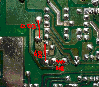
The "R4" resistor seems ok. It is giving me 48 ohm, and it is indeed a 5W, 47 ohm resistor.
The disc cap however, was shorted in circuit. I took it out and it is not shorted, but the pads it was on are still shorted. I measured a voltage drop of 0.048 (err... volts?), and resistance of 48 ohm.
I also noticed that those pads are shorted to the transformer leg with 0.03 ohm resistance. Not sure if that's ok..., but I guess it explains why there is a short (or at least 48 ohm resistance) across the cap.