VOGONS


First post, by ksiumaxx

User metadata
Rank Newbie
Rank
Newbie

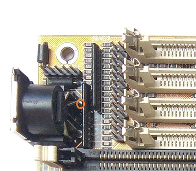
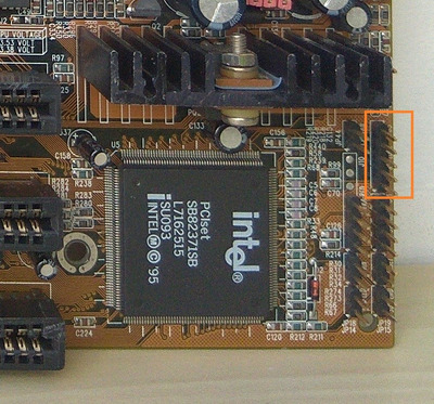
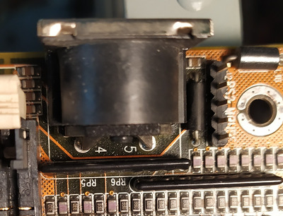
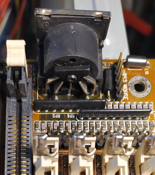
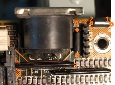
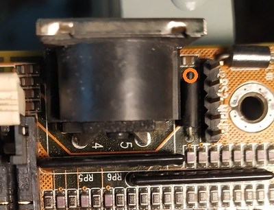
Hi. I have a PCPartner MB520NH motherboard which I would really want to use for my dos pc, but it's not detecting any keyboard I try. Din5, PS2->Din5 adapter failed, even tho all of the keyboards I tried are working, and get detected on other systems. When I boot the pc, lights on the keyboard don't flash once like they should, and it shows on the screen Keyboard error or no keyboard present. I saw this Keyboard error or no keyboard present post where they mentioned about a keylock jumper on the board, but I couldn't find any mention about it in the manual. The also mentioned about a keyboard fuse, which should be somewhere near the keyboard connector, but I wasn't able to locate it.
And I also have a question, which I couldn't find answer for even tho it could make using this motherboard much easier for me. If I would be able to make keyboards work again, could it be possible to replace Din5 connector with PS/2? I know I can just use a simple adapter, but adapters like that are not using any electronics, only wires so it should be doable.

Here you can find a manual and some specification about the motherboard: https://theretroweb.com/motherboards/s/pcpart … 20-03#downloads

Reply 1 of 21, by bogdanpaulb

User metadata
Rank Member
Rank
Member

You can check with a multi meter the presence of +5v on the DIN5 connector on the selected pin.
The location of the KB lock connector it's in the manual, and is shown in the second picture.

Attachments

  • testk.jpg
    Filename
    testk.jpg
    File size
    118.16 KiB
    Views
    829 views
    File license
    Fair use/fair dealing exception
  • keylock connector.jpg
    Filename
    keylock connector.jpg
    File size
    250.39 KiB
    Views
    829 views
    File license
    Fair use/fair dealing exception

Reply 3 of 21, by bogdanpaulb

User metadata
Rank Member
Rank
Member

Can you confirm: motherboard was turned on, multimeter was set on continuous voltage (e.g. 20v dc) and you used ground for the second lead of the multimeter ?

Reply 4 of 21, by Repo Man11

User metadata
Rank Oldbie
Rank
Oldbie

When looking at the back of the motherboard you ought to be able to follow the trace from the DIN connector to the keyboard fuse. I have a PCChips M520 where the issue was a bad solder joint on the keyboard fuse and the solder joints for the DIN connector were cracked.

"I'd rather be rich than stupid" - Jack Handey

Reply 5 of 21, by ksiumaxx

User metadata
Rank Newbie
Rank
Newbie
bogdanpaulb wrote on 2023-04-25, 15:35:

Can you confirm: motherboard was turned on, multimeter was set on continuous voltage (e.g. 20v dc) and you used ground for the second lead of the multimeter ?

Yes

Reply 6 of 21, by bogdanpaulb

User metadata
Rank Member
Rank
Member
ksiumaxx wrote on 2023-04-25, 16:27:
bogdanpaulb wrote on 2023-04-25, 15:35:

Can you confirm: motherboard was turned on, multimeter was set on continuous voltage (e.g. 20v dc) and you used ground for the second lead of the multimeter ?

Yes

Can you post a picture with the area from the first picture (DIN5 connector area) front and back of your motherboard ?

Reply 7 of 21, by ksiumaxx

User metadata
Rank Newbie
Rank
Newbie
bogdanpaulb wrote on 2023-04-25, 16:32:
ksiumaxx wrote on 2023-04-25, 16:27:
bogdanpaulb wrote on 2023-04-25, 15:35:

Can you confirm: motherboard was turned on, multimeter was set on continuous voltage (e.g. 20v dc) and you used ground for the second lead of the multimeter ?

Yes

Can you post a picture with the area from the first picture (DIN5 connector area) front and back of your motherboard ?

IMG_20230425_183905.jpg
Filename
IMG_20230425_183905.jpg
File size
371.92 KiB
Views
764 views
File license
Public domain
IMG_20230425_183915.jpg
Filename
IMG_20230425_183915.jpg
File size
355.47 KiB
Views
764 views
File license
Public domain
IMG_20230425_183951.jpg
Filename
IMG_20230425_183951.jpg
File size
794.4 KiB
Views
764 views
File license
Public domain

Reply 8 of 21, by bogdanpaulb

User metadata
Rank Member
Rank
Member

With power on, check with a multimeter the presence of 5v dc at all the points marked, careful not to short anything.

Attachments

  • key.jpg
    Filename
    key.jpg
    File size
    40.87 KiB
    Views
    756 views
    File license
    Fair use/fair dealing exception

Reply 9 of 21, by ksiumaxx

User metadata
Rank Newbie
Rank
Newbie

So yeah my multimetemer wasn't in the correct mode. The Din connector isn't getting 5V on any of the pins, and the ones you marked got:
1. 5.10V
2. 5.10V
3. 5.11V
4. Top one got 5.10V and bottom got 0.69V

Reply 10 of 21, by bogdanpaulb

User metadata
Rank Member
Rank
Member

Again, just to be sure, what was the voltage on the pins of the 'black' component ? Because you gave 2 values for nr.4.

Attachments

  • key.jpg
    Filename
    key.jpg
    File size
    40.03 KiB
    Views
    725 views
    File license
    Fair use/fair dealing exception
Last edited by bogdanpaulb on 2023-04-25, 18:04. Edited 1 time in total.

Reply 11 of 21, by ksiumaxx

User metadata
Rank Newbie
Rank
Newbie
bogdanpaulb wrote on 2023-04-25, 17:56:

Again, just to be sure, what was the voltage on that pin of the 'black' component ? Because you gave 2 values for nr.4.

Becouse you marked 2 sides of the black thing before. The one you marked now got 5.10V

Reply 18 of 21, by bogdanpaulb

User metadata
Rank Member
Rank
Member

Then search on the scrap/dead ones for a fuse and replace it ( the black component ). You should be able to find it in the same area of the motherboard, just post some pictures of what you found so you will not use a ferrite bead instead (they look very similar, the other 'black' component with pins 1 and 2).